
Page 197 - Advances in Renewable Energies and Power Technologies
P. 197
170 CHAPTER 5 DMPPT PV System: Modeling and Control Techniques
central inverters share the wrong opinion that because in PV applications adopting
microconverters the MPPT is distributed on the PV modules, the MPPT hardware
of the central inverter can be disabled or, better, the central inverter can be without
CMPPT control circuitry.
That’s why some commercial PV inverters (e.g., SolarEdge), adopted in PV ap-
plications using microconverters, operate with a fixed value of the DC input voltage
(the value where the inverter exhibits its peak efficiency). Instead, as it will be deeply
discussed in the following sections, the adoption of a proper CMPPT technique
coupled to a proper DMPPT technique is absolutely necessary. The term proper
here means that both the CMPPT technique and the DMPPT technique must be
correctly designed to avoid possible errors or malfunctioning during their working.
Regarding the DMPPT technique, a modified version of the P&O technique will be
adopted. Such a technique is able not only to track the MPP but also to face and solve
the problem of the limitation of the LSCPVUs output voltage. To avoid possible er-
rors of the CMPPT technique during the working of the PV system, such a technique
must be properly designed to consider the effect played by the particular shape
exhibited by the PeV characteristic of the string of LSCPVUs. In fact, the shape
of the PeV characteristic of a string of LSCPVUs, in case of mismatching operating
conditions, is characterized by the presence of multiple peaks, flat regions, and/or
nearly vertical portions [54,55]. Such features are able to lead to the error all the
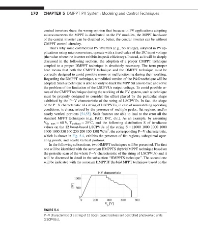
standard MPPT techniques (e.g., P&O, INC, etc.). As an example, by assuming
V ds max ¼ 60 V, T ambient ¼ 25 C, and the following distribution S of irradiance
values on the 12 boost-based LSCPVUs of the string S ¼ [1000 1000 1000 1000
2
1000 1000 350 300 250 200 150 150] W/m , the corresponding PeV characteristic,
which is shown in Fig. 5.4, exhibits the presence of flat regions, suboptimal oper-
ating points, and nearly vertical portions.
In the following subsections, two HMPPT techniques will be presented. The first
one will be identified with the acronym HMPPTS (hybrid MPPT technique based on
the periodic scan of the whole PeV characteristic of the string of LSCPVUs) and it
will be discussed in detail in the subsection “HMPPTS technique”. The second one
will be indicated with the acronym HMPPTF [hybrid MPPT technique based on the
FIGURE 5.4
PeV characteristic of a string of 12 boost-based lossless self controlled photovoltaic units
(LSCPVUs).