
Page 193 - Advances in Renewable Energies and Power Technologies
P. 193
166 CHAPTER 5 DMPPT PV System: Modeling and Control Techniques
from all the others, in the rest of this chapter the attention will be focused, without
any loss of generality, on techniques for modeling single strings of LSCPVUs. More-
over, in the rest of this chapter, again without any loss of generality, the three basic
DC/DC converters (buck, boost, and buckeboost) with synchronous rectification
and input-voltage feedback control will be considered [45], as shown in Fig. 5.1.
Microconverters based on the above basic topologies are the most widely available
on the market [47e51]. The presence of the input voltage feedback controller (PV
voltage compensation network) allows to avoid that every disturbance introduced on
the output voltage of an LSCPVU, by the inverter and/or by other LSCPVUs,
directly propagates on the PV modules’ output voltage causing instability or dy-
namic performance degradation [45,46]. The PV voltage compensation network
of Fig. 5.1 processes the error between the k-th PV voltage v pank and the correspond-
ing reference voltage v pan ref k (k ¼ 1, 2, .,N) provided by the DMPPT controller.
The output control signal of the PV voltage compensation network drives the PWM
block. If the control loop is fast enough, disturbances acting on the output voltage of
a given LSCPVU do not significantly affect its operation [43,45,46]. The meaning
which, in this chapter, will be given to the term DMPPT has been already provided
above. The term Central MPPT (CMPPT) will be used instead with reference to an
MPPT technique acting on the output voltage of a whole string of LSCPVUs.
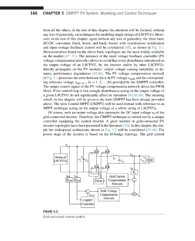
Of course, such an output voltage also represents the DC input voltage v b of the
grid-connected inverter. Therefore, the CMPPT technique is carried out by a unique
controller equipping the central inverter. A great number of grid-connected PV
inverter topologies have been presented in the literature [52]. In this chapter, the sim-
ple but widespread architecture shown in Fig. 5.2 will be considered [45,46]. The
power stage of the inverter is based on the H-bridge topology. The grid current
FIGURE 5.2
Grid-connected inverter system.