
Page 192 - Advances in Renewable Energies and Power Technologies
P. 192
2. Central Maximum Power Point Tracking and Distributed Maximum 165
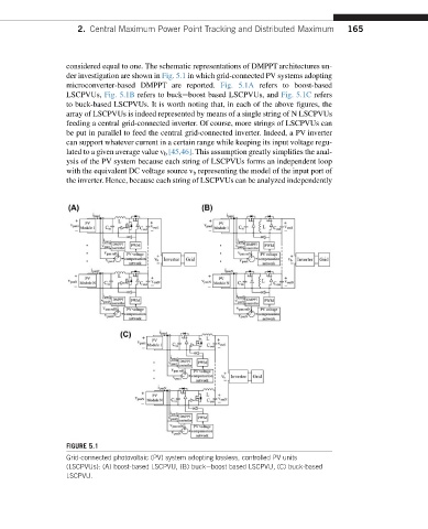
considered equal to one. The schematic representations of DMPPT architectures un-
der investigation are shown in Fig. 5.1 in which grid-connected PV systems adopting
microconverter-based DMPPT are reported. Fig. 5.1A refers to boost-based
LSCPVUs, Fig. 5.1B refers to buckeboost based LSCPVUs, and Fig. 5.1C refers
to buck-based LSCPVUs. It is worth noting that, in each of the above figures, the
array of LSCPVUs is indeed represented by means of a single string of N LSCPVUs
feeding a central grid-connected inverter. Of course, more strings of LSCPVUs can
be put in parallel to feed the central grid-connected inverter. Indeed, a PV inverter
can support whatever current in a certain range while keeping its input voltage regu-
lated to a given average value v b [45,46]. This assumption greatly simplifies the anal-
ysis of the PV system because each string of LSCPVUs forms an independent loop
with the equivalent DC voltage source v b representing the model of the input port of
the inverter. Hence, because each string of LSCPVUs can be analyzed independently
FIGURE 5.1
Grid-connected photovoltaic (PV) system adopting lossless, controlled PV units
(LSCPVUs): (A) boost-based LSCPVU, (B) buckeboost based LSCPVU, (C) buck-based
LSCPVU.