
Page 195 - Advances in Renewable Energies and Power Technologies
P. 195
168 CHAPTER 5 DMPPT PV System: Modeling and Control Techniques
active switch of a boost converter, during its OFF subinterval, is equal to the output
voltage [53]. The voltage across the active switch of a buckeboost converter, during
its OFF subinterval, is equal to the sum of the input and output voltages [53].To
avoid that the voltage stress of a device of one or more LSCPVUs exceeds V ds
max , an output voltage limitation technique needs to be adopted in the case of boost
and buckeboost converters [43,57]. Of course, no output voltage limitation tech-
nique is needed in the case of buck converters. In the case of the buckeboost and
buck topologies also switch current limitation techniques need to be adopted to
avoid that the currents in the switches may exceed I ds max [55,57,58]. To limit the
currents of the switches of a buckeboost converter or of a buck converter fed by
a PV module, it is possible to adopt for the duty-cycle a time-varying lower threshold
equal to the ratio i pan /I ds max , where i pan is the current of the PV module [55]. In this
chapter and, in particular, in Section 3.2.3, our attention will be focused on the
output voltage limitation technique only, because it deserves particular care in the
case of boost-based LSCPVUs, which are the subject of the time-domain numerical
simulations discussed in the following. Another parameter imposing additional con-
straints, which must be fulfilled to avoid limiting the energetic efficiency perfor-
mances of PV systems adopting microconverters, is represented by the value
assumed by the bulk inverter voltage v b [54e56,58]. To clarify the above statement,
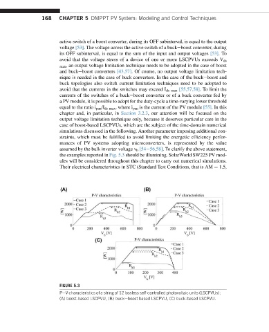
the examples reported in Fig. 5.3 should be illumining. SolarWorld SW225 PV mod-
ules will be considered throughout this chapter to carry out numerical simulations.
Their electrical characteristics in STC (Standard Test Conditions, that is AM ¼ 1.5,
FIGURE 5.3
PeV characteristics of a string of 12 lossless self-controlled photovoltaic units (LSCPVUs):
(A) boost-based LSCPVU, (B) buckeboost based LSCPVU, (C) buck-based LSCPVU.