
Page 196 - Advances in Renewable Energies and Power Technologies
P. 196
3. Necessity of Joint Adoption of Distributed Maximum Power Point 169
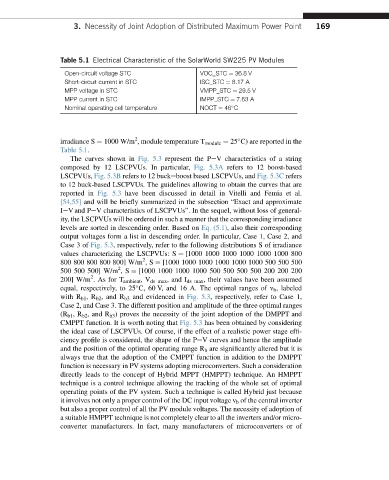
Table 5.1 Electrical Characteristic of the SolarWorld SW225 PV Modules
Open-circuit voltage STC VOC_STC ¼ 36.8 V
Short-circuit current in STC ISC_STC ¼ 8.17 A
MPP voltage in STC VMPP_STC ¼ 29.5 V
MPP current in STC IMPP_STC ¼ 7.63 A
Nominal operating cell temperature NOCT ¼ 46 C
2
irradiance S ¼ 1000 W/m , module temperature T module ¼ 25 C) are reported in the
Table 5.1.
The curves shown in Fig. 5.3 represent the PeV characteristics of a string
composed by 12 LSCPVUs. In particular, Fig. 5.3A refers to 12 boost-based
LSCPVUs, Fig. 5.3B refers to 12 buckeboost based LSCPVUs, and Fig. 5.3C refers
to 12 buck-based LSCPVUs. The guidelines allowing to obtain the curves that are
reported in Fig. 5.3 have been discussed in detail in Vitelli and Femia et al.
[54,55] and will be briefly summarized in the subsection “Exact and approximate
IeV and PeV characteristics of LSCPVUs”. In the sequel, without loss of general-
ity, the LSCPVUs will be ordered in such a manner that the corresponding irradiance
levels are sorted in descending order. Based on Eq. (5.1), also their corresponding
output voltages form a list in descending order. In particular, Case 1, Case 2, and
Case 3 of Fig. 5.3, respectively, refer to the following distributions S of irradiance
values characterizing the LSCPVUs: S ¼ [1000 1000 1000 1000 1000 1000 800
2
800 800 800 800 800] W/m ,S ¼ [1000 1000 1000 1000 1000 1000 500 500 500
2
500 500 500] W/m ,S ¼ [1000 1000 1000 1000 500 500 500 500 200 200 200
2
200] W/m . As for T ambient ,V ds max , and I ds max , their values have been assumed
equal, respectively, to 25 C, 60 V, and 16 A. The optimal ranges of v b , labeled
with R b1 ,R b2 , and R b3 and evidenced in Fig. 5.3, respectively, refer to Case 1,
Case 2, and Case 3. The different position and amplitude of the three optimal ranges
(R b1 ,R b2 , and R b3 ) proves the necessity of the joint adoption of the DMPPT and
CMPPT function. It is worth noting that Fig. 5.3 has been obtained by considering
the ideal case of LSCPVUs. Of course, if the effect of a realistic power stage effi-
ciency profile is considered, the shape of the PeV curves and hence the amplitude
and the position of the optimal operating range R b are significantly altered but it is
always true that the adoption of the CMPPT function in addition to the DMPPT
function is necessary in PV systems adopting microconverters. Such a consideration
directly leads to the concept of Hybrid MPPT (HMPPT) technique. An HMPPT
technique is a control technique allowing the tracking of the whole set of optimal
operating points of the PV system. Such a technique is called Hybrid just because
it involves not only a proper control of the DC input voltage v b of the central inverter
but also a proper control of all the PV module voltages. The necessity of adoption of
a suitable HMPPT technique is not completely clear to all the inverters and/or micro-
converter manufacturers. In fact, many manufacturers of microconverters or of