
Page 420 - Advances in Renewable Energies and Power Technologies
P. 420
4. Solar Thermal Energy Storage 393
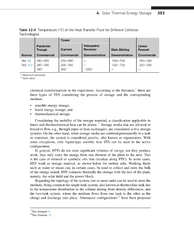
Table 12.4 Temperature ( C) of the Heat Transfer Fluid for Different Collector
Technologies
Tower
Parabolic Volumetric Linear
Trough Current Receiver Dish-Stirling Fresnel
Source Commercial Commercial Demonstration Demonstration Commercial
Ref. [9] 290e550 250e650 e 550e750 250e390
Ref. [12] 290e390 290e565 e 550e750 250e390
393 a 565 a 1000 b e e
a
Maximum achieved.
b
Goal value.
1
chemical transformations in the experiment. According to the literature, there are
three types of TES considering the process of storage and the corresponding
medium:
• sensible energy storage;
• latent energy storage; and
• thermochemical storage.
Considering the mobility of the storage material, a classification applicable to
latent and thermochemical heat can be drawn. 17 Storage media that are allowed or
forced to flow, e.g., through pipes or heat exchangers, are considered active storage
systems. On the other hand, when storage media are confined permanently in a tank
or container, the system is considered passive, also known as regenerators. With
some exceptions, only liquid-type sensible heat STS can be used in the active
configuration.
In general, HTFs do not store significant volumes of energy, nor they produce
work; they only carry the energy from one element of the plant to the next. This
is the case of mineral or synthetic oils that circulate along PTCs. In some cases,
HTF work as storage material, as shown below for molten salts. Working fluids
such as water or steam can, in certain cases, be used to collect and store the bulk
of the energy stored. HTF connects thermally the storage with the rest of the plant,
namely, the solar field and the power block.
Regarding the topology of the system, one or more tanks can be used to store the
medium, being common the single-tank system, also known as thermocline tank due
to the temperature distribution in the volume arising from density differences, and
the two-tank system, where the medium flows from one tank to the other as the
charge and discharge take place. Alternative configurations 18 have been proposed
17
See footnote 9.
18
See footnote 12.