
Page 70 - Advances in Renewable Energies and Power Technologies
P. 70
5. The PV Arrays 43
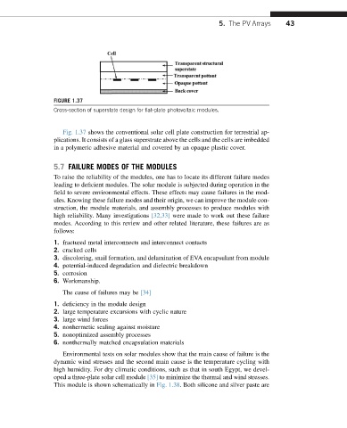
FIGURE 1.37
Cross-section of superstate design for flat-plate photovoltaic modules.
Fig. 1.37 shows the conventional solar cell plate construction for terrestrial ap-
plications. It consists of a glass superstrate above the cells and the cells are imbedded
in a polymeric adhesive material and covered by an opaque plastic cover.
5.7 FAILURE MODES OF THE MODULES
To raise the reliability of the modules, one has to locate its different failure modes
leading to deficient modules. The solar module is subjected during operation in the
field to severe environmental effects. These effects may cause failures in the mod-
ules. Knowing these failure modes and their origin, we can improve the module con-
struction, the module materials, and assembly processes to produce modules with
high reliability. Many investigations [32,33] were made to work out these failure
modes. According to this review and other related literature, these failures are as
follows:
1. fractured metal interconnects and interconnect contacts
2. cracked cells
3. discoloring, snail formation, and delamination of EVA encapsulant from module
4. potential-induced degradation and dielectric breakdown
5. corrosion
6. Workmanship.
The cause of failures may be [34]
1. deficiency in the module design
2. large temperature excursions with cyclic nature
3. large wind forces
4. nonhermetic sealing against moisture
5. nonoptimized assembly processes
6. nonthermally matched encapsulation materials
Environmental tests on solar modules show that the main cause of failure is the
dynamic wind stresses and the second main cause is the temperature cycling with
high humidity. For dry climatic conditions, such as that in south Egypt, we devel-
oped a three-plate solar cell module [35] to minimize the thermal and wind stresses.
This module is shown schematically in Fig. 1.38. Both silicone and silver paste are