
Page 137 - Aerodynamics for Engineering Students
P. 137
120 Aerodynamics for Engineering Students
Method (see Fig. 3.14)
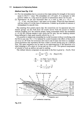
(1) Plot the streamlines due to a source at the origin taking the strength of the source
equal to 20m2s-' (say). The streamlines are n/lO apart. It is necessary to take
positive values of y only since the pattern is symmetrical about the Ox axis.
(2) Superimpose on the plot horizontal lines to a scale so that 1c, = -Uy = -1,
-2, -3, etc., are lines about 1 unit apart on the paper. Where the lines intersect,
add the values of 1c, at the lines of intersection. Connect up all points of constant 1c,
(streamlines) by smooth lines.
The resulting flow pattern shows that the streamlines can be separated into two
distinct groups: (a) the fluid from the source moves from the source to infinity
without mingling with the uniform stream, being constrained within the streamline
1c, = 0; (b) the uniform stream is split along the Ox axis, the two resulting streams
being deflected in their path towards infinity by 1c, = 0.
It is possible to replace any streamline by a solid boundary without interfering with
the flow in any way. If 1c, = 0 is replaced by a solid boundary the effects of the source
are truly cut off from the horizontal flow and it can be seen that here is a mathem-
atical expression that represents the flow round a curved fairing (say) in a uniform
flow. The same expression can be used for an approximation to the behaviour of a
wind sweeping in off a plain or the sea and up over a cliff. The upward components
of velocity of such an airflow are used in soaring.
The vertical velocity component at any point in the flow is given by -a$/ax. Now
- m atan-lb/x) ab/.)
&!J
___--
ax 2n ab/.) ax
9 due to source at origin
9 of combination streamlines
Fig. 3.14