
Page 171 - Aerodynamics for Engineering Students
P. 171
154 Aerodynamics for Engineering Students
7 The components DX and DY of R~Q are calculated in terms of the x and y
coordinates.
8 The components of RPQ in terms of the coordinate system based on panelj are
then calculated as
4
-+ -+
XQ = R~Q. and YQ = R~Q
.iij
9 VX and VY (i.e. vxn and vm) are evaluated using Eqns (3.97) and (3.98).
10 iii . 4, rii - iij, ?i 4, and ii fij are evaluated.
a
11 Finally the influence coefficients are evaluated from Eqn (3.99).
The routine presented above is primarily intended for educational purposes and
has not been optimized to economize on computing time. Nevertheless, using a
computer program based on the above routine and LU decomposition, accurate
computations of the pressure distribution around two-dimensional aerofoils can be
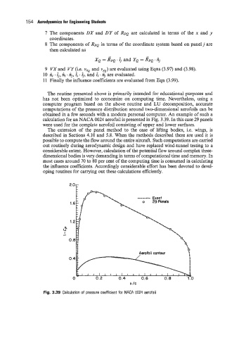
obtained in a few seconds with a modern personal computer. An example of such a
calculation for an NACA 0024 aerofoil is presented in Fig. 3.39. In this case 29 panels
were used for the complete aerofoil consisting of upper and lower surfaces.
The extension of the panel method to the case of lifting bodies, i.e. wings, is
described in Sections 4.10 and 5.8. When the methods described there are used it is
possible to compute the flow around the entire aircraft. Such computations are carried
out routinely during aerodynamic design and have replaced wind-tunnel testing to a
considerable extent. However, calculation of the potential flow around complex three-
dimensional bodies is very demanding in terms of computational time and memory. In
most cases around 70 to 80 per cent of the computing time is consumed in calculating
the influence coefficients. Accordingly considerable effort has been devoted to devel-
oping routines for carrying out these calculations efficiently.
x /c
Fig. 3.39 Calculation of pressure coefficient for NACA 0024 aerofoil