
Page 166 - Aerodynamics for Engineering Students
P. 166
Potential flow 149
where the integrals are to be understood as being carried out over the contour (or
surface) of the body. Until the advent of modern computers the result (3.89) was of
relatively little practical use. Owing to the power of modern computers, however, it
has become the basis of a computational technique that is now commonplace in
aerodynamic design.
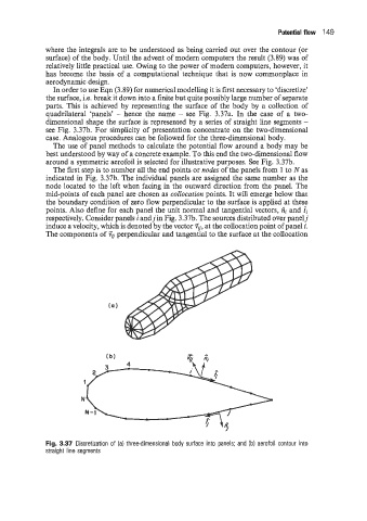
In order to use Eqn (3.89) for numerical modelling it is first necessary to ‘discretize’
the surface, i.e. break it down into a finite but quite possibly large number of separate
parts. This is achieved by representing the surface of the body by a collection of
quadrilateral ‘panels’ - hence the name - see Fig. 3.37a. In the case of a two-
dimensional shape the surface is represented by a series of straight line segments -
see Fig. 3.37b. For simplicity of presentation concentrate on the two-dimensional
case. Analogous procedures can be followed for the three-dimensional body.
The use of panel methods to calculate the potential flow around a body may be
best understood by way of a concrete example. To this end the two-dimensional flow
around a symmetric aerofoil is selected for illustrative purposes. See Fig. 3.37b.
The first step is to number all the end points or nodes of the panels from 1 to N as
indicated in Fig. 3.37b. The individual panels are assigned the same number as the
node located to the left when facing in the outward direction from the panel. The
mid-points of each panel are chosen as coZIocation points. It will emerge below that
the boundary condition of zero flow perpendicular to the surface is applied at these
points. Also define for each panel the unit normal and tangential vectors, fii and ii
respectively. Consider panels i andj in Fig. 3.37b. The sources distributed over panelj
induce a velocity, which is denoted by the vector ?q, at the collocation point of panel i.
The components of ?g perpendicular and tangential to the surface at the collocation
Fig. 3.37 Discretization of (a) three-dimensional body surface into panels; and (b) aerofoil contour into
straight line segments