
Page 79 - Aerodynamics for Engineering Students
P. 79
62 Aerodynamics for Engineering Students
i.e.
1 2 1
PI + -pv, +PPI =p2 + -pv; + pgzz
2 2
In the foregoing analysis 1 and 2 were completely arbitrary choices, and therefore
the same equation must apply to conditions at any other points. Thus
1
p + -pv2 + pgz = constant (2.16)
2
This is Bernoulli’s equation for an incompressible fluid, Le. a fluid that cannot
be compressed or expanded, and for which the density is invariable. Note that
Eqn (2.16) can be applied more generally to two- and three-dimensional steady flows,
provided that viscous effects are neglected. In the more general case, however, it is
important to note that Bernoulli’s equation can only be applied along a streamline,
and in certain cases the constant may vary from streamline to streamline.
2.2.2 Comments on the momentum and energy equations
Referring back to Eqn (2.8), that expresses the conservation of momentum in
algebraic form,
/ f + v2 + gz = constant
the first term is the internal energy of unit mass of the air, 4 v2 is the kinetic energy of
unit mass and gz is the potential energy of unit mass. Thus, Bernoulli’s equation in
this form is really a statement of the principle of conservation of energy in the
absence of heat exchanged and work done. As a corollary, it applies only to flows
where there is no mechanism for the dissipation of energy into some form not
included in the above three terms. In aerodynamics a common form of energy
dissipation is that due to viscosity. Thus, strictly the equation cannot be applied in
this form to a flow where the effects of viscosity are appreciable, such as that in a
boundary layer.
2.3 The measurement of air speed
2.3.1 The Pit6t-static tube
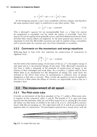
Consider an instrument of the form sketched in Fig. 2.7, called a Pit6t-static tube.
It consists of two concentric tubes A and B. The mouth of A is open and faces
directly into the airstream, while the end of B is closed on to A, causing B to be sealed
off. Some very fine holes are drilled in the wall of B, as at C, allowing B to commu-
nicate with the surrounding air. The right-hand ends of A and B are connected to
opposite sides of a manometer. The instrument is placed into a stream of air, with the
Fig. 2.7 The simple Pit&-sat c tube