
Page 169 - Aeronautical Engineer Data Book
P. 169
140 Aeronautical Engineer’s Data Book
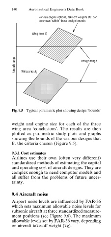
Various engine options, take-off weights etc. can
be shown ‘within’ these design bounds
Wing area S 1
Aircraft range Wing area S 2 Design range
Fig. 9.5 Typical parametric plot showing design ‘bounds’
weight and engine size for each of the three
wing area ‘conclusions’. The results are then
plotted as parametric study plots and graphs
showing the bounds of the various designs that
fit the criteria chosen (Figure 9.5).
9.3.1 Cost estimates
Airlines use their own (often very different)
standardized methods of estimating the capital
and operating cost of aircraft designs. They are
complex enough to need computer models and
all suffer from the problems of future uncer
tainty.
9.4 Aircraft noise
Airport noise levels are influenced by FAR-36
which sets maximum allowable noise levels for
subsonic aircraft at three standardized measure
ment positions (see Figure 9.6). The maximum
allowable levels set by FAR-36 vary, depending
on aircraft take-off weight (kg).