
Page 274 - Aeronautical Engineer Data Book
P. 274
220 Aeronautical Engineer’s Data Book
?
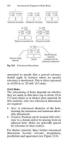
10 +0.05 10 nominal 10 +0.05 10 +1.00 10 +0.05 10 +0.05
-0.00 -0.00 -0.00 -0.00 -0.00
Tolerances incomplete 'Unbalanced' tolerances Tolerance clash
20 +0.100
20 +0.001
-0.000
-0.000
+0.005 +0.005 +0.0005 +0.0005
10 10 10 10
-0.000 -0.000 -0.0000 -0.0000
Tolerance inconsistencies Tolerances too tight
20 +0.100
-0.000
10 +0.05 10 +0.05
-0.00 -0.00
Overall tolerance
(optional)
Tolerance values
Correct consistent with the
balanced
toleranced components
Fig. 12.5 Toleranced dimensions
annotated to specify that a general tolerance
should apply to features where no specific
tolerance is mentioned. This is often expressed
as ±0.020 in or ‘20 mils’ (0.5 mm).
12.4.2 Holes
The tolerancing of holes depends on whether
they are made in thin sheet (up to about 1/8 in
(3.2 mm) thick) or in thicker plate material. In
thin material, only two toleranced dimensions
are required:
• Size: A toleranced diameter of the hole,
showing the maximum and minimum allow
able dimensions.
• Position: Position can be located with refer
ence to a datum and/or its spacing from an
adjacent hole. Holes are generally spaced
by reference to their centres.
For thicker material, three further toleranced
dimensions become relevant: straightness,
parallelism and squareness (see Figure 12.6).