
Page 279 - Aeronautical Engineer Data Book
P. 279
Basic mechanical design 225
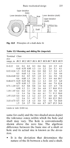
Upper deviation
(hole)
Lower deviation (hole) Lower deviation (shaft)
Hole
Upper deviation
(shaft)
Basic size Shaft Basic size Zero line
Fig. 12.8 Principles of a shaft–hole fit
Table 12.5 Running and sliding fits (imperial)
Nominal Class
size
range, in RC1 RC2 RC3 RC4 RC5 RC6 RC7 RC8 RC9
0–0.12 0.1 0.1 0.3 0.3 0.6 0.6 1.0 2.5 4.0
0.45 0.55 0.95 1.3 1.6 2.2 2.6 5.1 8.1
0.12–0.24 1.5 0.15 0.4 0.4 0.8 0.8 1.2 2.8 4.5
0.5 0.65 1.2 1.6 2.0 2.7 3.1 5.8 9.0
0.24–0.40 0.2 0.2 0.5 0.5 1.0 1.0 1.6 3.0 5.0
0.6 0.85 1.5 2.0 2.5 3.3 3.9 6.6 10.7
0.40–0.71 0.25 0.25 0.6 0.6 1.2 1.2 2.0 3.5 6.0
0.75 0.95 1.7 2.3 2.9 3.8 4.6 7.9 12.8
0.71–1.19 0.3 0.3 0.8 0.8 1.6 1.6 2.5 4.5 7.0
0.95 1.2 2.1 2.8 3.6 4.8 5.7 10.0 15.5
1.19–1.97 0.4 0.4 1.0 1.0 2.0 2.0 3.0 5.0 8.0
1.1 1.4 2.6 3.6 4.6 6.1 7.1 11.5 18.0
1.97–3.15 0.4 0.4 1.2 1.2 2.5 2.5 4.0 6.0 9.0
1.2 1.6 3.1 4.2 5.5 7.3 8.8 13.5 20.5
3.15–4.73 0.5 0.5 1.4 1.4 3.0 3.0 5.0 7.0 10.0
1.5 2.0 3.7 5.0 6.6 8.7 10.7 15.5 24.0
Limits in ‘mils’ (0.001 in).
same for each) and the two shaded areas depict
the tolerance zones within which the hole and
shaft may vary. The hole is conventionally
shown above the zero line. The algebraic
difference between the basic size of a shaft or
hole and its actual size is known as the devia
tion.
• It is the deviation that determines the
nature of the fit between a hole and a shaft.