
Page 310 - Air Pollution Control Engineering
P. 310
05_chap_wang.qxd 05/05/2004 3:51 pm Page 289
Wet and Dry Scrubbing 289
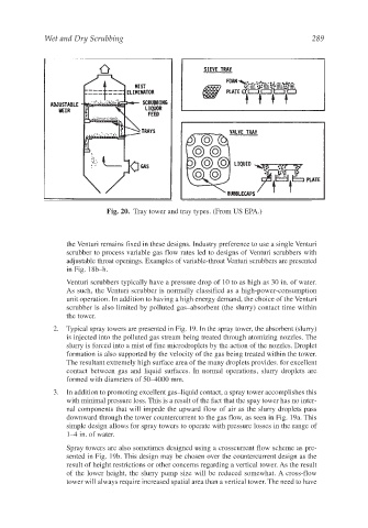
Fig. 20. Tray tower and tray types. (From US EPA.)
the Venturi remains fixed in these designs. Industry preference to use a single Venturi
scrubber to process variable gas flow rates led to designs of Venturi scrubbers with
adjustable throat openings. Examples of variable-throat Venturi scrubbers are presented
in Fig. 18b–h.
Venturi scrubbers typically have a pressure drop of 10 to as high as 30 in. of water.
As such, the Venturi scrubber is normally classified as a high-power-consumption
unit operation. In addition to having a high energy demand, the choice of the Venturi
scrubber is also limited by polluted gas–absorbent (the slurry) contact time within
the tower.
2. Typical spray towers are presented in Fig. 19. In the spray tower, the absorbent (slurry)
is injected into the polluted gas stream being treated through atomizing nozzles. The
slurry is forced into a mist of fine microdroplets by the action of the nozzles. Droplet
formation is also supported by the velocity of the gas being treated within the tower.
The resultant extremely high surface area of the many droplets provides. for excellent
contact between gas and liquid surfaces. In normal operations, slurry droplets are
formed with diameters of 50–4000 mm.
3. In addition to promoting excellent gas–liquid contact, a spray tower accomplishes this
with minimal pressure loss. This is a result of the fact that the spay tower has no inter-
nal components that will impede the upward flow of air as the slurry droplets pass
downward through the tower countercurrent to the gas flow, as seen in Fig. 19a. This
simple design allows for spray towers to operate with pressure losses in the range of
1–4 in. of water.
Spray towers are also sometimes designed using a crosscurrent flow scheme as pre-
sented in Fig. 19b. This design may be chosen over the countercurrent design as the
result of height restrictions or other concerns regarding a vertical tower. As the result
of the lower height, the slurry pump size will be reduced somewhat. A cross-flow
tower will always require increased spatial area than a vertical tower. The need to have