Page 381 - Air Pollution Control Engineering
P. 381

08_chap_wang.qxd  05/05/2004  4:26 pm  Page 357
                    Thermal Oxidation                                                         357
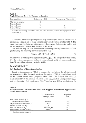
                    Table 5
                    Typical Pressure Drops for Thermal Incinerators
                    Equipment type              Heat recovery (HR)        Pressure drop P (in. H O)
                                                                                            2
                    Thermal incinerator                0                           4
                    Heat exchanger                     35                          4
                    Heat exchanger                     50                          8
                    Heat exchanger                     70                          15

                       Note: The pressure drop is calculated as the sum of the incinerator and heat-exchanger pressure drops.
                       Source: ref. 2.


                       An accurate estimate of system pressure drop would require complex calculations. A
                    preliminary estimate can be made using the approximate values listed in Table 5. The
                    system pressure drop is the sum of the pressure drops across the incinerator and the heat
                    exchanger plus the pressure drop through the ductwork.
                       The pressure drop can then be used to estimate the power requirement for the flue
                    gas fan using the following empirical correlation (12):
                                                        ×
                                            Power =1.17 10  –4  × Q fg  × P ε                  (7)
                    where Power is the fan power requirement (kWh), Q is the flue gas flow rate (scfm),
                                                                   fg
                    P is the system pressure drop (inches of water column), and ε is the combined motor
                    fan efficiency (dimensionless [typically 60%]).

                    5. MANAGEMENT

                    5.1. Evaluation of Permit Application
                       Permit evaluators can use Table 6 to compare the results from the calculations and
                    the values supplied by the permit applicant. The values in Table 6 are calculated based
                    on the emission stream 1 example presented in Table 1. The flue gas flow rate (Q )
                                                                                               fg
                    is determined from the emission stream flow rate (Q ), dilution air requirement (Q ),
                                                                    e                          d
                    and supplementary fuel requirement (Q ). Therefore, any differences between the
                                                         f

                    Table 6
                    Comparison of Calculated Values and Values Supplied by the Permit Applicant for
                    Thermal Incineration
                                                          Calculated value         Reported
                                                          (example case) a           value
                    Continuous monitoring of
                      combustion temperature                 163 scfm                 —
                    Supplementary fuel flowrate, Q             Yes                    —
                                              f
                    Dilution airflow rate, Q                    0                     —
                                       d
                    Flue gas flow rate, Q                   15,200 scfm               —
                                     fg
                    Combustion chamber volume, V              840 ft 3                —
                                              c
                       a Based on emission stream 1.
   376   377   378   379   380   381   382   383   384   385   386