
Page 39 - Air Pollution Control Engineering
P. 39
01_chap_wang.qxd 05/05/2004 11:45 am Page 19
Air Quality and Pollution Control 19
choose the longest straight section in the area where the sample is to be taken. Ideally,
the sample location should be at least 15-pipe diameters downstream from the last bend
or obstruction and 10-pipe diameters upstream from any opening, bend, or obstruction.
The US EPA has suggested guidelines (6) that can be followed for increasing the num-
ber of traverse points at any sample location, depending on how near obstructions are
to sample locations. These instructions are essential for good particulate sampling.
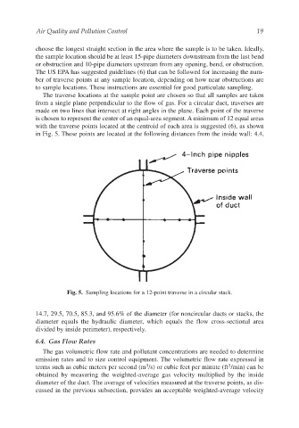
The traverse locations at the sample point are chosen so that all samples are taken
from a single plane perpendicular to the flow of gas. For a circular duct, traverses are
made on two lines that intersect at right angles in the plane. Each point of the traverse
is chosen to represent the center of an equal-area segment. A minimum of 12 equal areas
with the traverse points located at the centroid of each area is suggested (6), as shown
in Fig. 5. These points are located at the following distances from the inside wall: 4.4,
Fig. 5. Sampling locations for a 12-point traverse in a circular stack.
14.7, 29.5, 70.5, 85.3, and 95.6% of the diameter (for noncircular ducts or stacks, the
diameter equals the hydraulic diameter, which equals the flow cross-sectional area
divided by inside perimeter), respectively.
6.4. Gas Flow Rates
The gas volumetric flow rate and pollutant concentrations are needed to determine
emission rates and to size control equipment. The volumetric flow rate expressed in
3
3
terms such as cubic meters per second (m /s) or cubic feet per minute (ft /min) can be
obtained by measuring the weighted-average gas velocity multiplied by the inside
diameter of the duct. The average of velocities measured at the traverse points, as dis-
cussed in the previous subsection, provides an acceptable weighted-average velocity