
Page 41 - Air Pollution Control Engineering
P. 41
01_chap_wang.qxd 05/05/2004 11:45 am Page 21
Air Quality and Pollution Control 21
the velocity pressure. Methods of obtaining static pressure are shown in Fig. 6. The sim-
ple through-the-wall tap (Fig. 6A) is a sharp, burr-free tubing located perpendicular to
and flush with the inside wall. This is good for nonturbulent systems, and like all
sampling devices, it must be kept free of liquid (condensate, entrained liquid, etc.). Method
B utilizes a pipe with radially drilled holes, and because it is located away from the wall
disturbances, it is good for velocities up to 12,000 ft/min. Systems with high dust loads
may require a device, shown by Method C, which gives a rapid response and also
responds best to low pressure.
Asmooth, sharp-edged impact tube facing directly into the gas stream, as shown in
Fig. 7, can be attached to the “high” side of a manometer and a static pressure connec-
tion attached to the “low” side. This shows velocity pressure (P ) directly on the
v
manometer. An inclined manometer as shown in Fig. 7 can be used for improving accu-
racy in reading a low-pressure drop (∆P). Any other type of pressure gage or manometer
can be used. The connections between the tubes and the gage must be kept tight and free
of liquid.
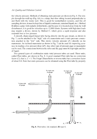
Two general types of combination static–total pressure tubes are used. These units,
called Pitot tubes, are shown in Fig. 8. A good standard Pitot tube has no correction
factor (C); that is, C = 1. The S-type (Stauscheibe or reverse tube) has a correction factor
of about 0.8. Note that static pressures can be obtained using the Pitot tube by properly
Fig. 8. Pitot tubes: (A) standard; (B) type S.