Page 410 - Air Pollution Control Engineering
P. 410

09_chap_wang.qxd  05/05/2004  5:01 pm  Page 383
                    Catalytic Oxidation                                                       383
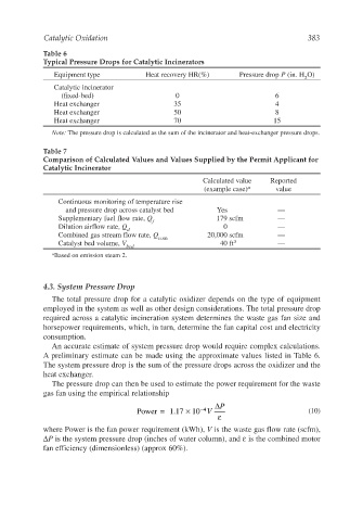
                    Table 6
                    Typical Pressure Drops for Catalytic Incinerators
                       Equipment type            Heat recovery HR(%)       Pressure drop P (in. H O)
                                                                                             2
                       Catalytic incinerator
                         (fixed-bed)                     0                           6
                       Heat exchanger                   35                           4
                       Heat exchanger                   50                           8
                       Heat exchanger                   70                          15
                       Note: The pressure drop is calculated as the sum of the incinerator and heat-exchanger pressure drops.

                    Table 7
                    Comparison of Calculated Values and Values Supplied by the Permit Applicant for
                    Catalytic Incinerator
                                                                Calculated value   Reported
                                                                 (example case) a    value
                        Continuous monitoring of temperature rise
                          and pressure drop across catalyst bed     Yes              —
                        Supplementary fuel flow rate, Q             179 scfm         —
                                                  f
                        Dilution airflow rate, Q                      0              —
                                           d
                        Combined gas stream flow rate, Q          20,000 scfm        —
                                                    com
                        Catalyst bed volume, V                       40 ft 3         —
                                           bed
                       a Based on emission steam 2.

                    4.3. System Pressure Drop

                       The total pressure drop for a catalytic oxidizer depends on the type of equipment
                    employed in the system as well as other design considerations. The total pressure drop
                    required across a catalytic incineration system determines the waste gas fan size and
                    horsepower requirements, which, in turn, determine the fan capital cost and electricity
                    consumption.
                       An accurate estimate of system pressure drop would require complex calculations.
                    A preliminary estimate can be made using the approximate values listed in Table 6.
                    The system pressure drop is the sum of the pressure drops across the oxidizer and the
                    heat exchanger.
                       The pressure drop can then be used to estimate the power requirement for the waste
                    gas fan using the empirical relationship
                                                                    ∆ P
                                                                −
                                              Power =  1.17 ×  10 V                           (10)
                                                                 4
                                                                     ε
                    where Power is the fan power requirement (kWh), V is the waste gas flow rate (scfm),
                    ∆P is the system pressure drop (inches of water column), and ε is the combined motor
                    fan efficiency (dimensionless) (approx 60%).
   405   406   407   408   409   410   411   412   413   414   415