
Page 413 - Air Pollution Control Engineering
P. 413
09_chap_wang.qxd 05/05/2004 5:01 pm Page 386
386 Lawrence K. Wang et al.
with respect to future “clean” standards is ever present, as the perception that the man-
agers must attain zero concentration is still held by some stakeholders.
This is one of the areas where risk management and environmental compliance meet.
A structured, planned approach to managing incidents is one of the most successful
ways to control liabilities. The risk management process provides a framework for man-
aging environmental liabilities. It is composed of the identification, quantification, and
ultimate treatment of loss exposures. Two of the primary objectives of risk management
are to control losses and to minimize the financial impacts resulting from the loss. There
are several strategies that can be used singularly or in combination that enable the risk
manager to accomplish these objectives. Indelicato has outlined these strategies as they
pertain to the control of environmental liabilities or losses (22).
Many environmental concerns have been managed on a postloss basis using some form
of health-based risk assessment or risk-based corrective action (RBCA). This approach
provides strategies for managing environmental risk ranging from total cleanup to back-
ground level (or below a specified detection limit) to minor cleanup of “hot” spots with
30 yr of monitoring for any changes to the environment as a result of some low level of
the contaminant being left in place.
The RBCA strategy provides for a cost-effective solution to minimizing the impacts to
the public and the environment as a result of the contamination. Follow-up legal docu-
mentation from the state regulatory agency allows for a degree of certainty that the envi-
ronmental liability is controlled and that business can proceed in a risk-managed manner.
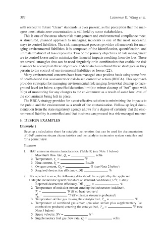
6. DESIGN EXAMPLES
Example 1
Develop a calculation sheet for catalytic incineration that can be used for documentation
of HAP emission stream characteristics and the catalytic incinerator system variables and
for a permit view.
Solution
1. HAP emission stream characteristics: (Table 8) (see Note 1 below)
1. Maximum flow rate, Q = scfm
e
2. Temperature, T = ºF
e
3. Heat content, h = Btu/lb
e
4. Oxygen content, O = % (see Note 2 below)
2
5. Required destruction efficiency, DE %
2. For a permit review, the following data should be supplied by the applicant:
Catalytic incinerator system variables at standard conditions (77ºF, 1 atm):
1. Reported destruction efficiency, DE = %
reported
2. Temperature of emission stream entering the incinerator (oxidizer),
T = ºF (if no heat recovery)
e
T = ºF (if emission stream is preheated)
he
3. Temperature of flue gas leaving the catalytic bed, T = ºF
co
4. Temperature of combined gas stream (emission stream plus supplementary fuel
combustion products) entering the catalyst bed, T = ºF (see
ci
Note 3 below)
5. Space velocity, SV = h −1
6. Supplementary fuel gas flow rate, Q = scfm
f