
Page 220 - Air pollution and greenhouse gases from basic concepts to engineering applications for air emission control
P. 220
196 7 Combustion Process and Air Emission Formation
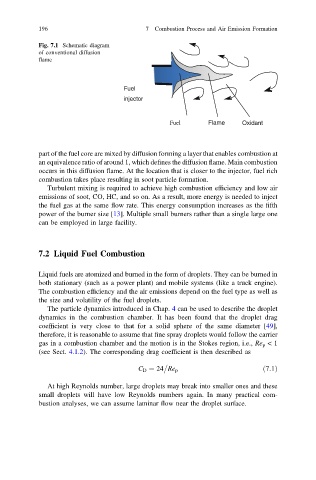
Fig. 7.1 Schematic diagram
of conventional diffusion
flame
Fuel
injector
Fuel Flame Oxidant
part of the fuel core are mixed by diffusion forming a layer that enables combustion at
an equivalence ratio of around 1, which defines the diffusion flame. Main combustion
occurs in this diffusion flame. At the location that is closer to the injector, fuel rich
combustion takes place resulting in soot particle formation.
Turbulent mixing is required to achieve high combustion efficiency and low air
emissions of soot, CO, HC, and so on. As a result, more energy is needed to inject
the fuel gas at the same flow rate. This energy consumption increases as the fifth
power of the burner size [13]. Multiple small burners rather than a single large one
can be employed in large facility.
7.2 Liquid Fuel Combustion
Liquid fuels are atomized and burned in the form of droplets. They can be burned in
both stationary (such as a power plant) and mobile systems (like a truck engine).
The combustion efficiency and the air emissions depend on the fuel type as well as
the size and volatility of the fuel droplets.
The particle dynamics introduced in Chap. 4 can be used to describe the droplet
dynamics in the combustion chamber. It has been found that the droplet drag
coefficient is very close to that for a solid sphere of the same diameter [49],
therefore, it is reasonable to assume that fine spray droplets would follow the carrier
gas in a combustion chamber and the motion is in the Stokes region, i.e., Re p <1
(see Sect. 4.1.2). The corresponding drag coefficient is then described as
C D ¼ 24 Re p ð7:1Þ
At high Reynolds number, large droplets may break into smaller ones and these
small droplets will have low Reynolds numbers again. In many practical com-
bustion analyses, we can assume laminar flow near the droplet surface.