
Page 108 - Air and Gas Drilling Manual
P. 108
3-36 Air and Gas Drilling Manual
Fire float valves and fire stop valves are used only for oil and natural gas
recovery drilling operations.
The fire stop valves are placed just above the drill bit and along the drill string
at several positions. These valves have a zinc ring that holds back a spring-loaded
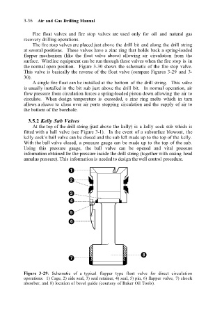
flapper mechanism (like the float valve above) allowing air circulation from the
surface. Wireline equipment can be run through these valves when the fire stop is in
the normal open position. Figure 3-30 shows the schematic of the fire stop valve.
This valve is basically the reverse of the float valve (compare Figures 3-29 and 3-
30).
A single fire float can be installed at the bottom of the drill string. This valve
is usually installed in the bit sub just above the drill bit. In normal operation, air
flow pressure from circulation forces a spring-loaded piston down allowing the air to
circulate. When design temperature is exceeded, a zinc ring melts which in turn
allows a sleeve to close over air ports stopping circulation and the supply of air to
the bottom of the borehole.
3.5.2 Kelly Sub Valves
At the top of the drill string (just above the kelly) is a kelly cock sub which is
fitted with a ball valve (see Figure 3-1). In the event of a subsurface blowout, the
kelly cock’s ball valve can be closed and the sub left made up to the top of the kelly.
With the ball valve closed, a pressure gauge can be made up to the top of the sub.
Using this pressure gauge, the ball valve can be opened and vital pressure
information obtained for the pressure inside the drill string (together with casing head
annulus pressure). This information is needed to design the well control procedure.
1
2
3
4
5
6
8
7
Figure 3-29: Schematic of a typical flapper type float valve for direct circulation
operations. 1) Cage, 2) side seal, 3) seal retainer, 4) seal, 5) pin, 6) flapper valve, 7) shock
absorber, and 8) location of bevel guide (courtesy of Baker Oil Tools).