
Page 109 - Air and Gas Drilling Manual
P. 109
Chapter 3: Downhole Equipment 3-37
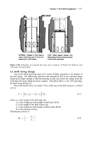
Figure 3-30: Schematic of a typical fire stop valve (courtesy of Wayne M. Sullivan and
Associates Incorporated).
3.6 Drill String Design
One of the initial planning steps for a rotary drilling operation is the design of
the drill string. The drill string must have the strength to drill to the intended target
depth and be light enough so that the hoisting system can extract the string from the
well when the target depth has been reached. Described below is the API procedure
for drill string design [1].
The axial tension force (or load), F (lb), at the top of the drill string in a vertical
well is
F = ( L w p) + ( L w ) K (3-1)
p c c b
where L p is the length of the drill pipe (ft),
w p is the weight per unit length of drill pipe (lb/ft),
L c is the length of the drill collars (ft),
w c is the weight per unit length of drill collars (lb/ft),
K b is the buoyancy factor.
The buoyancy factor is
γ m
K b = 1 − (3-2)
γ s 