
Page 107 - Air and Gas Drilling Manual
P. 107
Chapter 3: Downhole Equipment 3-35
In general dual wall pipe elements are structurally very rigid and stiff. Thus,
this type of pipe can be used in compression. This eliminates the need for heavy
drill collars to place WOB in a reverse circulation, dual wall pipe drilling operation.
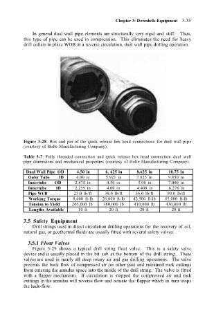
Figure 3-28: Box and pin of the quick release hex head connections for dual wall pipe
(courtesy of Holte Manufacturing Company).
Table 3-7: Fully threaded connection and quick release hex head connection dual wall
pipe dimensions and mechanical properties (courtesy of Holte Manufacturing Company).
Dual Wall Pipe OD 4.50 in 6. 625 in 8.625 in 10.75 in
Outer Tube ID 4.00 in 5.921 in 7.825 in 9.850 in
Innertube OD 2.875 in 4.50 in 5.00 in 7.000 in
Innertube ID 2.259 in 4.00 in 4.408 in 6.276 in
Pipe Wt/ft 23.0 lb/ft 39.0 lb/ft 56.0 lb/ft 90.0 lb/ft
Working Torque 8,000 ft-lb 26,000 ft-lb 42,500 ft-lb 85,000 ft-lb
Tension to Yield 205,000 lb 380,000 lb 410,000 lb 430,000 lb
Lengths Available 10 ft 20 ft 20 ft 20 ft
3.5 Safety Equipment
Drill strings used in direct circulation drilling operations for the recovery of oil,
natural gas, or geothermal fluids are usually fitted with several safety valves.
3.5.1 Float Valves
Figure 3-29 shows a typical drill string float valve. This is a safety valve
device and is usually placed in the bit sub at the bottom of the drill string. These
valves are used in nearly all deep rotary air and gas drilling operations. The valve
prevents the back flow of compressed air (or other gas) and entrained rock cuttings
from entering the annulus space into the inside of the drill string. The valve is fitted
with a flapper mechanism. If circulation is stopped the compressed air and rock
cuttings in the annulus will reverse flow and actuate the flapper which in turn stops
the back-flow.