
Page 188 - Air and Gas Drilling Manual
P. 188
5-30 Air and Gas Drilling Manual
503
.27
. )
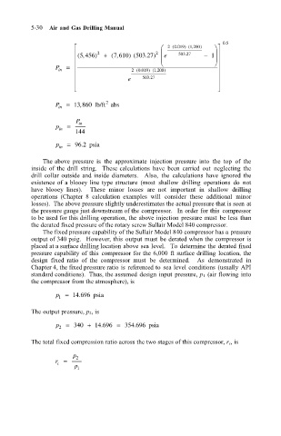
P in = (, 5 456 ) 2 + ( , 7 610 ) (503 27 2 e ) 2 (. 0 019 ) ( , 1 200 ) − 1 . 05
2
) ( , 1 200
(. 0 019
e 503 .27
2
P in = 13 860 lb/ft abs
,
P in
p in =
144
.
p in = 96 2 psia
The above pressure is the approximate injection pressure into the top of the
inside of the drill string. These calculations have been carried out neglecting the
drill collar outside and inside diameters. Also, the calculations have ignored the
existence of a blooey line type structure (most shallow drilling operations do not
have blooey lines). These minor losses are not important in shallow drilling
operations (Chapter 8 calculation examples will consider these additional minor
losses). The above pressure slightly underestimates the actual pressure that is seen at
the pressure gauge just downstream of the compressor. In order for this compressor
to be used for this drilling operation, the above injection pressure must be less than
the derated fixed pressure of the rotary screw Sullair Model 840 compressor.
The fixed pressure capability of the Sullair Model 840 compressor has a pressure
output of 340 psig. However, this output must be derated when the compressor is
placed at a surface drilling location above sea level. To determine the derated fixed
pressure capability of this compressor for the 6,000 ft surface drilling location, the
design fixed ratio of the compressor must be determined. As demonstrated in
Chapter 4, the fixed pressure ratio is referenced to sea level conditions (usually API
standard conditions). Thus, the assumed design input pressure, p 1 (air flowing into
the compressor from the atmosphere), is
p = 14 696 psia
.
1
The output pressure, p 2, is
p 2 = 340 + 14 696 = 354 696 psia
.
.
The total fixed compression ratio across the two stages of this compressor, r c, is
p
r = 2
c
p 1