Page 462 - Air and Gas Drilling Manual
P. 462
9-66    Air and Gas Drilling Manual
                                            537 66.˚R
                                      T
                                       av1
                                   In  order  to  obtain  the  approximate  value  of  the  Fanning  friction  factor  for
                               Equation 6-82, it is necessary to  estimate the Reynolds number and, thus,  the flow
                               conditions  inside  the  drill  pipe  body  lumped  geometry  along  H 1.    This  is
                               accomplished by determining the Reynolds number at the entrance end of the inside
                               of this  drill  string  section  and  assuming  this  Reynolds  number  approximates  the
                               flow conditions throughout the inside this drill string section.
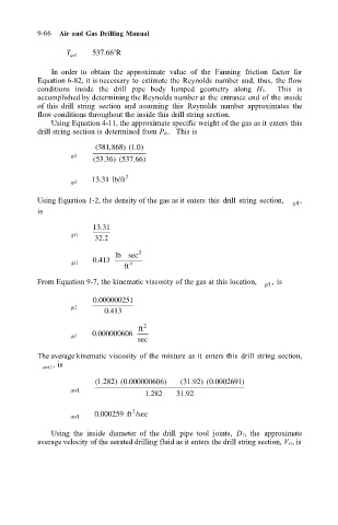
                                   Using Equation 4-11, the approximate specific weight of the gas as it enters this
                               drill string section is determined from P in.   This is
                                             ( 381 868) ( 1 0)
                                                ,
                                                      .
                                       gi1
                                            ( 53 36) ( 537 66)
                                                      .
                                               .
                                            13 31 lb/ft  3
                                              .
                                       gi1
                               Using Equation 1-2, the density of the gas as it enters this  drill  string section,   ,
                                                                                           gi1
                               is
                                            13 31
                                              .
                                       gi1
                                             32 2
                                               .
                                                  lb sec 2
                                             .
                                            0 413
                                       gi1           4
                                                    ft
                               From Equation 9-7, the kinematic viscosity of the gas at this location,   gi1 , is
                                            0 000000251
                                             .
                                       gi1
                                                .
                                               0 413
                                                        2
                                                       ft
                                             .
                                            0 000000606
                                       gi1
                                                       sec
                               The average kinematic viscosity of the mixture as it  enters this  drill  string section,
                                   , is
                                 avi1
                                                                        .
                                                    .
                                              .
                                                                   .
                                             ( 1 282)( 0 000000606)  ( 31 92)( 0 0002691)
                                       avi1
                                                        1 282   31 92
                                                                  .
                                                         .
                                                      2
                                             0 000259 ft /sec
                                              .
                                       avi1
                                   Using  the  inside  diameter  of  the  drill  pipe  tool  joints,  D 7,  the  approximate
                               average velocity of the aerated drilling fluid as it enters the drill string section, V i1, is

