Page 484 - Air and Gas Drilling Manual
P. 484
Chapter 10: Stable Foam drilling    10-9
                                            w ˙
                                      Q
                                       g
                                             P f g  T av w ˙  s  H  P bh P bh  P s g  H Q f  (10-1)
                                                     ln
                                                 T g     P s
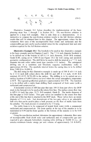
                                   Illustrative  Example  10.1  below  describes  the  implementation  of  the  basic
                               planning  steps  Nos.  1  through  7  in  Section  10.1.    The  non-friction  solution  is
                               applied  to  a  deep  well  example.    This  is  only  done  as  a  demonstration.    It  is
                               instructive to  compare the non-friction solution  results to  the full  friction  solution
                               results that will  be obtained later in  this  chapter.  The  approximate  values  for  the
                               volumetric  flow  rates  of  the  incompressible  fluid  (water  and  surfactant)  and  the
                               compressible gas (air) can be used as initial values for the complicated trial and error
                               solution required for the full friction solution.
                                   Illustrative Example 10.1  The borehole to be used in this  illustrative example
                               is the basic example used in Chapters 8 and 9.  The 7  7/8 inch diameter borehole is
                               to  be drilled out  of the bottom  of API 8  5/8  inch  diameter,  28.00  lb/ft  nominal,
                               Grade H-40, casing set to  7,000  ft (see Figure  10-2  for  well  casing  and  openhole
                               geometric configuration).  The drill bit to be used to drill the interval is a 7 7/8 inch
                               diameter  tri-cone  roller  cutter  insert  type  (nozzles  9/32  inches).    The  anticipated
                               drilling  rate  in  a  sandstone  and  limestone  sequence  (sedimentary  rock)  is
                               approximate 60 ft/hr.   The openhole interval below the casing shoe is  to  be drilled
                               from 7,000 ft to 10,000 ft.
                                   The drill string for this illustrative example is  made up of 500 ft of 6  3/4 inch
                               by 2  13/16 inch drill  collars above  the  drill  bit  and  API  4  1/2  inch,  16.60  lb/ft
                               nominal, EU-S135, NC50 (IF) to the surface.   The drilling  is  to  be carried out  at a
                               surface location of 4,000 ft above sea level where the actual atmospheric temperature
                               is 60˚F.  The regional geothermal gradient is approximately 0.01˚F/ft.   The borehole
                               is  to  be drilled with  a stable foam drilling  fluid  composed  of  fresh  water  (with  a
                               surfactant) and compressed air.
                                   A horizontal section of API line pipe that runs 100 ft from just  above the BOP
                               stack to the burn pit is to be used as the return flow line. The surface return flow line
                               is API 6 5/8 inch  line pipe,  32.71  lb/ft  nominal,  Grade B.    The inside diameter of
                               this line pipe is 5.625 inches.  Two gate valves are installed in  the return flow line
                               at the end of the line that is attached to the BOP stack.  These valves have an inside
                               diameter of 5  9/16 inch.    Just  downstream of the two gate valves is  an  adjustable
                               ball valve that can be used to place a back pressure on the flow of stable foam from
                               the annulus.  The back pressure is assumed to be 17.0 psig.
                                   The stable foam is  to  be composed of  treated  fresh  water  (with  a  commercial
                               surfactant) and compressed air.  The foam quality at the top  of the annulus is  to  be
                               maintained at 0.98 and the foam quality at the bottom  of the annulus is  to  be 0.60
                               or greater.
                                   Using the non-friction method, determine the approximate volumetric flow rates
                               of  incompressible  fluid  (fresh  water  and  surfactant)  and  of  compressible  gas  (air)
                               required to  give adequate bottomhole  cleaning while drilling  at  10,000  ft  (i.e.,  an
                                                                                            3
                               annulus minimum  kinetic  energy  per  unit  volume  of  approximately  3.0  ft-lb/ft ).

