Page 504 - Air and Gas Drilling Manual
P. 504
Chapter 10: Stable Foam drilling    10-29
                               lengths  will  be  “lumped”  together  as  a  continuous  length  to  approximate  their
                               contribution to the overall major (wall friction) loss  in  the flow system.    Thus,  the
                               drill pipe tool joints of the drill pipe in the 7,000 ft cased section of the borehole are
                               calculated as a “lump” at the bottom of this cased section.  The drill  pipe tool  joints
                               of the drill pipe in the 2,500  ft openhole section of the borehole are calculated as a
                               “lump” at the bottom of this openhole section.
                                    These lumped approximations for the drill pipe tool joints  are somewhat rough
                               approximations, but  will  give accurate bottomhole and injection  pressures.    Using
                               this  lumped approximation, the pressure terms  along  the  annulus  around  the  drill
                               pipe and inside the drill  pipe are in  error by a  few  percent.    However,  this  short-
                               coming can obviously  be relieved  by  calculating  a  short  1  1/2  ft  long  tool  joint
                               every 30 ft along the entire drill  pipe length of the drill  string.   This  can easily be
                               accomplished  with  a  sophisticated  computer  program.    But  these  lumped
                               approximations  are  very  useful  in  demonstrating  the  calculation  technique  steps.
                               These  lumped  approximations  are  very  easy  to  incorporate  in  an  engineering
                               calculation program and it has been found that these approximations are adequate for
                               most engineering practice applications.
                                   The calculation sequence for this illustrative example is  divided into  five depth
                               increments.  The increments start at the top  of the borehole with  the first increment
                               at the top and the fifth increment at the bottom.
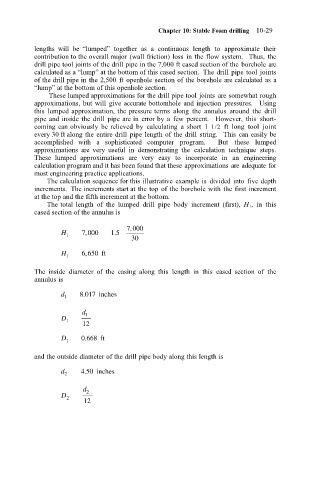
                                   The total length  of  the  lumped  drill  pipe  body  increment  (first),  H 1,  in  this
                               cased section of the annulus is
                                                       7 000
                                                        ,
                                            ,
                                      H 1   7 000  1 5 .
                                                        30
                                            ,
                                      H 1   6 650 ft
                               The  inside  diameter  of  the  casing  along  this  length  in  this  cased  section  of  the
                               annulus is
                                            .
                                      d 1  8 017 inches
                                            d 1
                                      D 1
                                            12
                                      D 1  0 668 ft
                                            .
                               and the outside diameter of the drill pipe body along this length is

                                      d    450 inches
                                            .
                                       2
                                            d 2
                                      D 2
                                            12

