
Page 56 - Air and Gas Drilling Manual
P. 56
2-6 Air and Gas Drilling Manual
pressure gauge. For air drilling operations this mud gauge must be replaced with a
high quality gas gauge having the appropriate pressure range.
2.2.7 Volumetric FlowRate Meters
No driller would carry out a mud drilling operation without knowing the
volumetric flow rate of mud being circulated to the well. The volumetric flow rate
from a mud pump can be easily assessed by either counting strokes per minute of the
mud pump (and knowing the capacity of the pump in gallons per stroke and then
calculating the output of the pump in gallons per minute), or by providing the rig
floor with an accurate volumetric flow rate gauge.
The volumetric flow rate of air (or other gases) to the well is vital knowledge for
a successful drilling operation and its knowledge must also be made available to the
rig personnel. Volumetric flow rate of air (or other gases) is referenced to the
atmospheric conditions of the air entering the primary compressor. At sea level
locations the volumetric flow rate is given as standard cubic feet per minute (scfm).
At locations above sea level the volumetric flow rate is given as actual cubic feet per
minute (acfm).
There are two techniques for determining the air volumetric flow rate from the
primary compressors (or natural gas from a pipeline). A gas production orifice plate
with associated recording system can be used in the flow line downstream of the
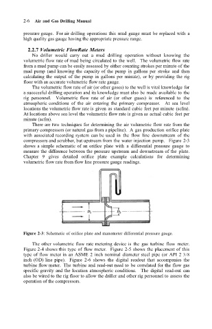
compressors and scrubber, but upstream from the water injection pump. Figure 2-3
shows a simple schematic of an orifice plate with a differential pressure gauge to
measure the difference between the pressure upstream and downstream of the plate.
Chapter 9 gives detailed orifice plate example calculations for determining
volumetric flow rate from flow line pressure gauge readings.
Figure 2-3: Schematic of orifice plate and manometer differential pressure gauge.
The other volumetric flow rate metering device is the gas turbine flow meter.
Figure 2-4 shows this type of flow meter. Figure 2-5 shows the placement of this
type of flow meter in an ASME 2 inch nominal diameter steel pipe (or API 2 3/8
inch (OD) line pipe). Figure 2-6 shows the digital readout that accompanies the
turbine flow meter. The turbine and read-out need to be correlated for the flow gas
specific gravity and the location atmospheric conditions. The digital read-out can
also be wired to the rig floor to allow the driller and other rig personnel to assess the
operation of the compressors.