
Page 59 - Air and Gas Drilling Manual
P. 59
Chapter 2: Surface Equipment 2-9
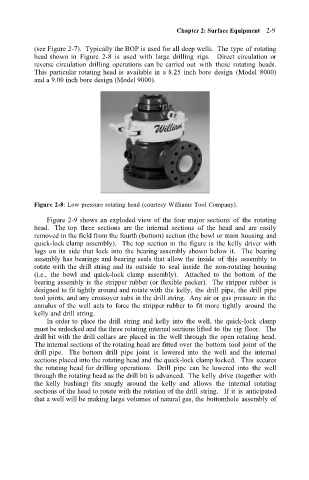
(see Figure 2-7). Typically the BOP is used for all deep wells. The type of rotating
head shown in Figure 2-8 is used with large drilling rigs. Direct circulation or
reverse circulation drilling operations can be carried out with these rotating heads.
This particular rotating head is available in a 8.25 inch bore design (Model 8000)
and a 9.00 inch bore design (Model 9000).
Figure 2-8: Low pressure rotating head (courtesy Williams Tool Company).
Figure 2-9 shows an exploded view of the four major sections of the rotating
head. The top three sections are the internal sections of the head and are easily
removed in the field from the fourth (bottom) section (the bowl or main housing and
quick-lock clamp assembly). The top section in the figure is the kelly driver with
lugs on its side that lock into the bearing assembly shown below it. The bearing
assembly has bearings and bearing seals that allow the inside of this assembly to
rotate with the drill string and its outside to seal inside the non-rotating housing
(i.e., the bowl and quick-lock clamp assembly). Attached to the bottom of the
bearing assembly is the stripper rubber (or flexible packer). The stripper rubber is
designed to fit tightly around and rotate with the kelly, the drill pipe, the drill pipe
tool joints, and any crossover subs in the drill string. Any air or gas pressure in the
annulus of the well acts to force the stripper rubber to fit more tightly around the
kelly and drill string.
In order to place the drill string and kelly into the well, the quick-lock clamp
must be unlocked and the three rotating internal sections lifted to the rig floor. The
drill bit with the drill collars are placed in the well through the open rotating head.
The internal sections of the rotating head are fitted over the bottom tool joint of the
drill pipe. The bottom drill pipe joint is lowered into the well and the internal
sections placed into the rotating head and the quick-lock clamp locked. This secures
the rotating head for drilling operations. Drill pipe can be lowered into the well
through the rotating head as the drill bit is advanced. The kelly drive (together with
the kelly bushing) fits snugly around the kelly and allows the internal rotating
sections of the head to rotate with the rotation of the drill string. If it is anticipated
that a well will be making large volumes of natural gas, the bottomhole assembly of