
Page 64 - Air and Gas Drilling Manual
P. 64
2-14 Air and Gas Drilling Manual
structure in a manner to prevent the well fluids from escaping to the surface through
either the inside of the drill pipe or around the outside of the drill pipe. This vise
like action of the two rams essentially forces the pipe to deform between the two
rams. The pipe ram acts in a somewhat similar manner as the blind ram. Except the
pipe ram has a geometric shape on the end of the rams that conform to the outside
surface of the drill pipe. Thus the pipe ram seals against the outside of the drill pipe
and prevents well fluids from escaping to the surface around the outside of the drill
pipe. The pipe ram does not fail the pipe structure, therefore, drilling mud can be
circulated down the inside of the drill pipe to safely allow the kick to be circulated
to the surface.
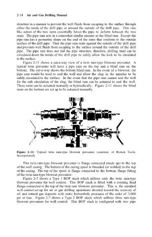
Figure 2-11 shows a cut-a-way view of a twin ram-type blowout preventer. A
typical twin preventer will have a pipe ram on the top and a blind ram on the
bottom. The cut-a-way shows the bottom blind ram. In the event of a blowout, the
pipe ram would be used to seal the well and allow the slug in the annulus to be
safely circulated to the surface. In the event that the pipe ram cannot seal the well
for the safe circulation of the slug, the blind ram can be actuated to seal the well.
These rams can be actuated manually or hydraulically. Figure 2-11 shows the blind
rams on the bottom are set up to be actuated manually.
Figure 2-11: Typical twin ram-type blowout preventer (courtesy of Bowen Tools,
Incorporated).
This twin ram-type blowout preventer is flange connected (made up) to the top
of the well casing. The bottom of the casing spool is threaded (or welded) to the top
of the casing. The top of the spool is flange connected to the bottom flange fitting
of the twin ram-type blowout preventer.
Figure 2-7 shows a Type 1 BOP stack which utilizes only the twin ram-type
blowout preventer for well control. This BOP stack is fitted with a rotating head
flange connected to the top of the twin ram blowout preventer. This is the standard
well control set up for air or gas drilling operations directed toward the recovery of
oil and natural gas deposits with static bottomhole pressures of the order of 3,000
psi or less. Figure 2-7 shows a Type 2 BOP stack which utilizes three ram-type
blowout preventers for well control. This BOP stack is configured with two pipe