
Page 68 - Air and Gas Drilling Manual
P. 68
2-18 Air and Gas Drilling Manual
2.4.2 Burn Pit
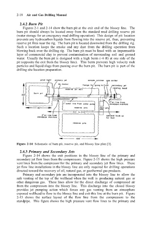
Figures 2-1 and 2-14 show the burn pit at the exit end of the blooey line. The
burn pit should always be located away from the standard mud drilling reserve pit
(water storage for an emergency mud drilling operation). This design of pit location
prevents any hydrocarbon liquids from flowing into the reserve pit, thus, preventing
reserve pit fires near the rig. The burn pit is located downwind from the drilling rig.
Such a location keeps the smoke and any dust from the drilling operation from
blowing back over the drilling rig. The burn pit must be lined with an impermeable
layer of commercial clay to prevent contamination of surrounding soil and ground
water. Usually the burn pit is designed with a high berm (~6 ft) at one side of the
pit (opposite the exit from the blooey line). This berm prevents high velocity rock
particles and liquid slugs from passing over the burn pit. The burn pit is part of the
drilling site location preparation.
Figure 2-14: Schematic of burn pit, reserve pit, and blooey line plan [3].
2.4.3 Primary and Secondary Jets
Figure 2-14 shows the exit positions in the blooey line of the primary and
secondary jet flow lines from the compressors. Figure 2-15 shows the high pressure
vent lines from the compressor for the primary and secondary jet flow lines. These
jet flow line installations in the blooey line are only required for drilling operations
directed toward the recovery of oil, natural gas, or geothermal gas products.
Primary and secondary jets are incorporated into the blooey line to allow the
safe venting of the top of the wellhead when the well is producing natural gas or
other dangerous gas. These lines allow for the direct discharge of compressed air
from the compressors into the blooey line. This discharge into the closed blooey
provides jet pumping action which forces any gas venting from an atmosphere
exposed wellhead to flow to the blooey line and exit this line at the burn pit. Figure
2-15 shows the surface layout of the flow line from the compressors to the
standpipe. This figure shows the high pressure vent flow lines to the primary and