
Page 66 - Air and Gas Drilling Manual
P. 66
2-16 Air and Gas Drilling Manual
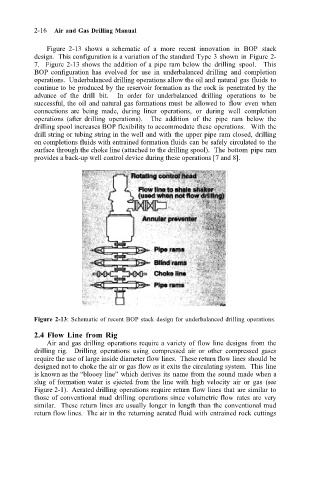
Figure 2-13 shows a schematic of a more recent innovation in BOP stack
design. This configuration is a variation of the standard Type 3 shown in Figure 2-
7. Figure 2-13 shows the addition of a pipe ram below the drilling spool. This
BOP configuration has evolved for use in underbalanced drilling and completion
operations. Underbalanced drilling operations allow the oil and natural gas fluids to
continue to be produced by the reservoir formation as the rock is penetrated by the
advance of the drill bit. In order for underbalanced drilling operations to be
successful, the oil and natural gas formations must be allowed to flow even when
connections are being made, during liner operations, or during well completion
operations (after drilling operations). The addition of the pipe ram below the
drilling spool increases BOP flexibility to accommodate these operations. With the
drill string or tubing string in the well and with the upper pipe ram closed, drilling
on completions fluids with entrained formation fluids can be safely circulated to the
surface through the choke line (attached to the drilling spool). The bottom pipe ram
provides a back-up well control device during these operations [7 and 8].
Figure 2-13: Schematic of recent BOP stack design for underbalanced drilling operations.
2.4 Flow Line from Rig
Air and gas drilling operations require a variety of flow line designs from the
drilling rig. Drilling operations using compressed air or other compressed gases
require the use of large inside diameter flow lines. These return flow lines should be
designed not to choke the air or gas flow as it exits the circulating system. This line
is known as the “blooey line” which derives its name from the sound made when a
slug of formation water is ejected from the line with high velocity air or gas (see
Figure 2-1). Aerated drilling operations require return flow lines that are similar to
those of conventional mud drilling operations since volumetric flow rates are very
similar. These return lines are usually longer in length than the conventional mud
return flow lines. The air in the returning aerated fluid with entrained rock cuttings