
Page 70 - Air and Gas Drilling Manual
P. 70
2-20 Air and Gas Drilling Manual
is advanced. This information allows the drilling operation to accurately drill to a
subsurface target area.
Figure 2-16: Typical sample catcher designs [3].
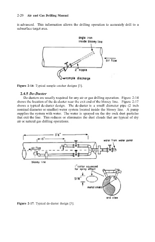
2.4.5 De-Duster
De-dusters are usually required for any air or gas drilling operation. Figure 2-14
shows the location of the de-duster near the exit end of the blooey line. Figure 2-17
shows a typical de-duster design. The de-duster is a small diameter pipe (2 inch
nominal diameter or smaller) water system located inside the blooey line. A pump
supplies the system with water. The water is sprayed on the dry rock dust particles
that exit the line. This reduces or eliminates the dust clouds that are typical of dry
air or natural gas drilling operations.
Figure 2-17: Typical de-duster design [3].