
Page 69 - Air and Gas Drilling Manual
P. 69
Chapter 2: Surface Equipment 2-19
secondary jets. The primary jet positioned near the exit end of the blooey line and
the secondary jet near the entrance end of the blooey line just downstream of the tee
from the annulus (see Figure 2-14).
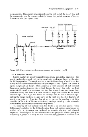
Figure 2-15: High pressure vent lines to the primary and secondary jets[3].
2.4.4 Sample Catcher
Sample catchers are usually required for any air and gas drilling operation. The
sample catcher allows small rock cutting samples to be obtained from a well during
the drilling operation. The sample catcher is installed in the body of the blooey line
usually near the entrance to the blooey line (see Figure 2-14). Figure 2-16 shows a
typical sample catcher design. This design has a small diameter (2 inch nominal
diameter or smaller) transport pipe welded through the blooey line body. A short
section of this small pipe protrudes into the flow stream inside the blooey line.
Inside the blooey line there is a short section of angle iron welded to the small
transport pipe. This angle iron directs the cuttings into the small transport pipe.
Outside the blooey line there is a gate valve on the small pipe to allow discharge of
sample rock cuttings. Since the flow of air or gas up the annulus is at high
velocities (of the order of 50 ft/sec to 80 ft/sec), cuttings sampling can be accurately
correlated to subsurface rock formations being drilled.
The securing of rock cuttings from the depths is an essential practice when
drilling deep boreholes. At the drilling location, these rock cuttings samples can be
studied under a microscope and analyzed to ascertain chemical and physical
properties. Knowledge of the rock characteristics and properties allows geologists
and drilling engineers to identify the rock formations being penetrated as the drill bit