
Page 650 - Air and Gas Drilling Manual
P. 650
12-14 Air and Gas Drilling Manual
accumulated rock cuttings. This agitation will force the rock cuttings into the
drilling fluid return flow stream in the annulus. Thus, drill string rotation promotes
more efficient horizontal borehole cleaning.
12.4.2 Sliding Drill String While Drilling
When directional corrections are being made, rotation is stopped, the drill string
is oriented so that the bent sub can be effective in correcting the directions of
drilling, and the drill string is slid along the low side of the borehole as the
downhole motor rotates the drill bit (allowing the drill bit to advance). Under this
operational situation the rock cuttings that might accumulate on the low side of the
hole will not be mechanically agitated and forced into the return flow stream above
the drill string. This operational situation is probably the worst case from the view
point of horizontal borehole cleaning. To analyze this particular operational
situation it will be necessary to draw on the pneumatic conveying literature [4]. For
horizontal pneumatic conveying, saltation occurs when the conveyed solids fall to
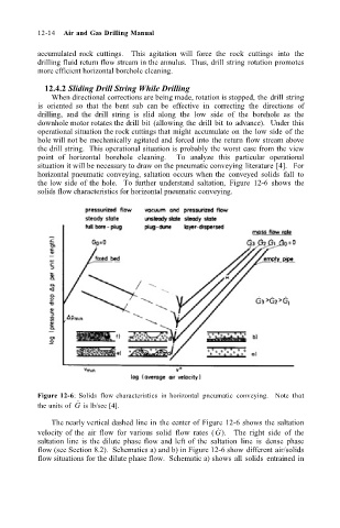
the low side of the hole. To further understand saltation, Figure 12-6 shows the
solids flow characteristics for horizontal pneumatic conveying.
Figure 12-6: Solids flow characteristics in horizontal pneumatic conveying. Note that
˙
the units of G is lb/sec [4].
The nearly vertical dashed line in the center of Figure 12-6 shows the saltation
˙
velocity of the air flow for various solid flow rates (G). The right side of the
saltation line is the dilute phase flow and left of the saltation line is dense phase
flow (see Section 8.2). Schematics a) and b) in Figure 12-6 show different air/solids
flow situations for the dilute phase flow. Schematic a) shows all solids entrained in