Page 654 - Air and Gas Drilling Manual
P. 654
12-18    Air and Gas Drilling Manual
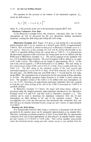
                                   The equation  for  the  pressure  at  the  bottom  of  the  horizontal  segment,  P ,
                               inside the drill string is
                                       en [
                                      P =   P ex 2  + 2  a b T av ] 05 .               (12-7) en
                                                          L
                                                      i
                                                    i
                                                                                2
                               where  P  is the pressure at the exit to the horizontal segment (lb/ft  abs).
                                     ex
                                 Minimum Volumetric Flow Rate
                                   In the illustrative example below, the minimum  volumetric  flow  rate  of  inert
                               atmospheric  air  will  be  discussed  for  the  two  directional  drilling  operational
                               situations, rotating the drill string and sliding the drill string.
                                   Illustrative Example 12.2  Figure 12-8 gives a well profile for a directionally
                               drilled borehole that is  to  be  initiated  at  a  kickoff  point  (KOP)  of  approximately
                               7,000 ft.  This well profile is similar to that given in Illustrative Example series 8.1,
                               8.2, and 8.3.  However, in this example the well will  be drilled directionally in  the
                               3,000 ft of openhole drilling  below the casing shoe at 7,000  ft.    It is  planned that
                               the directional segments of the well below the casing shore are to be drilled with  the
                               PDM used in Illustrative Example 11.2.   The curved segment of the openhole will
                               be a 318 ft medium radius borehole.  The curved segment will be drilled to  an angle
                               of 90˚ to the vertical.  This will give an arc length of approximately 500 ft.    At the
                               end of the curved segment, a 2,500 ft horizontal is to be drilled.  The drill  string in
                               the vertical cased section of the well is to be 4 1/2 inch, heavy-weight drill  pipe (see
                               Table  3-3).    The  drill  string  in  the  openhole  section  of  the  well  (curved  and
                               horizontal segments) is to be API 4 1/2 inch,  16.60  lb/ft  nominal,  EU-S135, NC50
                               (IF) drill pipe.  The MWD, bent sub, and PDM with a 7 7/8 inch drill bit will  make
                               up the BHA.  The anticipated rate of penetration for the directional drilling  operation
                               is  30 ft/hr.  The drilling  operation surface location is  at  4,000  ft  above  mean  sea
                               level.  The openhole section of the well is  to  be drilled with  inert atmospheric  air
                               (i.e., S g = 0.97).  Determine the approximate minimum volumetric flow rate required
                               to clean the well when drilling  at the end of the 2,500  ft horizontal (or 3,000  ft of
                               openhole drilling).
                                   In  Illustrative  Example  12.3  below,  the  major  and  minor  losses  solution  is
                               presented using  the lumped geometry approximations introduced in  the  Illustrative
                               Example series 8.3a and 8.3b,  and  also  used  in  Illustrative  Example  11.2.    This
                               solution  can  be  used  to  determine  the  minimum  volumetric  flow  rate  of  inert
                               atmospheric  air  while  drilling  at  the  end  of  the  openhole  section.    This  is
                               accomplished via a trial and error process that determines the  volumetric  flow  rate
                               that will give an annulus minimum kinetic energy per unit volume of approximately
                                       3
                               3.0 ft-lb/ft .
                                 Rotating the Drill String
                                   It is assumed that when the drill  string is  rotated in  a directional well the flow
                               geometry in the annulus space can be adequately approximated as an annulus flow.
                               Therefore, assuming an annulus geometry of flow, it was found that the approximate
                               volumetric flow rate of inert atmospheric air that will give an annulus kinetic energy
                                                      3
                               per unit  volume of 3.0  ft-lb/ft is  1,630  acfm.    This  critical  annulus  cross-section
                               where the minimum kinetic energy per unit  volume occurs is  just  up-hole from the

