
Page 651 - Air and Gas Drilling Manual
P. 651
Chapter 12: Directional Drilling Operations 12-15
the air flow. Schematic b) shows a small volume of the solids lying on the low side
of the horizontal flow duct, but the air flow with entrained solids flowing at steady
state conditions above slower moving low side steady state solids/air flow.
Schematics c), d), e), and f) show various stages of unsteady dense solids/air flow.
Clearly the minimum volumetric flow rate for the sliding drill string situation
in horizontal drilling should attempt to avoid excessive saltation. Sliding of the
drill string in the horizontal borehole is complicated by the actual borehole cross-
section geometry. When sliding the drill string will lay on the low side of the
borehole. Thus, the return flow in the borehole is not flow in an annulus. To give
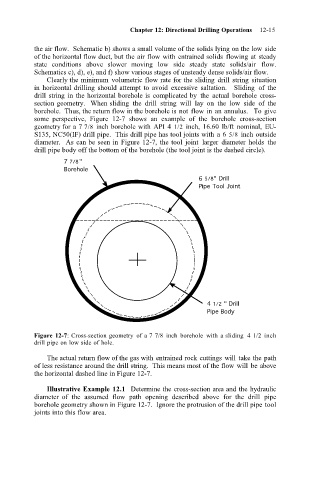
some perspective, Figure 12-7 shows an example of the borehole cross-section
geometry for a 7 7/8 inch borehole with API 4 1/2 inch, 16.60 lb/ft nominal, EU-
S135, NC50(IF) drill pipe. This drill pipe has tool joints with a 6 5/8 inch outside
diameter. As can be seen in Figure 12-7, the tool joint larger diameter holds the
drill pipe body off the bottom of the borehole (the tool joint is the dashed circle).
7 7/8"
Borehole
6 5/8" Drill
Pipe Tool Joint
4 1/2 " Drill
Pipe Body
Figure 12-7: Cross-section geometry of a 7 7/8 inch borehole with a sliding 4 1/2 inch
drill pipe on low side of hole.
The actual return flow of the gas with entrained rock cuttings will take the path
of less resistance around the drill string. This means most of the flow will be above
the horizontal dashed line in Figure 12-7.
Illustrative Example 12.1 Determine the cross-section area and the hydraulic
diameter of the assumed flow path opening described above for the drill pipe
borehole geometry shown in Figure 12-7. Ignore the protrusion of the drill pipe tool
joints into this flow area.