
Page 162 - Air and gas Drilling Field Guide 3rd Edition
P. 162
6.2 General Derivation 153
Three flow conditions can exist in the annulus. These are laminar, transitional,
and turbulent [1].
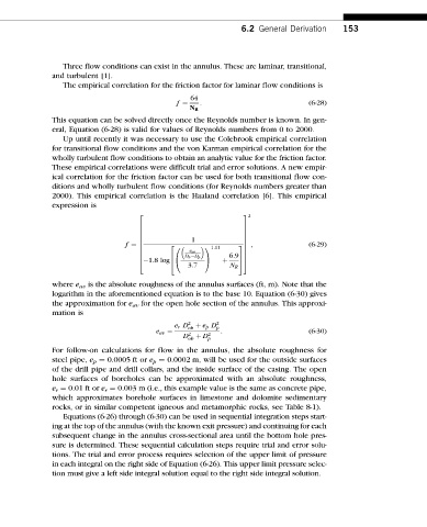
The empirical correlation for the friction factor for laminar flow conditions is
64
f ¼ N R : (6-28)
This equation can be solved directly once the Reynolds number is known. In gen-
eral, Equation (6-28) is valid for values of Reynolds numbers from 0 to 2000.
Up until recently it was necessary to use the Colebrook empirical correlation
for transitional flow conditions and the von Karman empirical correlation for the
wholly turbulent flow conditions to obtain an analytic value for the friction factor.
These empirical correlations were difficult trial and error solutions. A new empir-
ical correlation for the friction factor can be used for both transitional flow con-
ditions and wholly turbulent flow conditions (for Reynolds numbers greater than
2000). This empirical correlation is the Haaland correlation [6]. This empirical
expression is
2 3 2
7
6
6 7
6 7
1
6 7
f ¼ 6 2 3 7 ; (6-29)
11:11
0
6 7
e av
6 7
D h D p
6 6:97 7
6
@ A þ
4
1:8 log4 5 5
3:7 N R
where e av is the absolute roughness of the annulus surfaces (ft, m). Note that the
logarithm in the aforementioned equation is to the base 10. Equation (6-30) gives
the approximation for e av for the open hole section of the annulus. This approxi-
mation is
e r D 2 þ e p D 2
e av ¼ oh p : (6-30)
2
D oh þ D 2 p
For follow-on calculations for flow in the annulus, the absolute roughness for
steel pipe, e p ¼ 0.0005 ft or e p ¼ 0.0002 m, will be used for the outside surfaces
of the drill pipe and drill collars, and the inside surface of the casing. The open
hole surfaces of boreholes can be approximated with an absolute roughness,
e r ¼ 0.01 ft or e r ¼ 0.003 m (i.e., this example value is the same as concrete pipe,
which approximates borehole surfaces in limestone and dolomite sedimentary
rocks, or in similar competent igneous and metamorphic rocks, see Table 8-1).
Equations (6-26) through (6-30) can be used in sequential integration steps start-
ing at the top of the annulus (with the known exit pressure) and continuing for each
subsequent change in the annulus cross-sectional area until the bottom hole pres-
sure is determined. These sequential calculation steps require trial and error solu-
tions. The trial and error process requires selection of the upper limit of pressure
in each integral on the right side of Equation (6-26). This upper limit pressure selec-
tion must give a left side integral solution equal to the right side integral solution.