
Page 50 - Air and gas Drilling Field Guide 3rd Edition
P. 50
3.2 Flow Line to the Rig 41
D 1 D 2
FIGURE 3-3. Schematic of orifice plate and manometer differential pressure gauge.
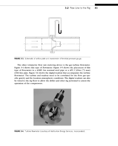
The other volumetric flow rate metering device is the gas turbine flowmeter.
Figure 3-4 shows this type of flowmeter. Figure 3-5 shows the placement of this
type of flowmeter in a ASME 2-in nominal steel pipe or a API 2 3/8-in (73 mm)
(OD) line pipe. Figure 3-6 shows the digital readout that accompanies the turbine
flowmeter. The turbine and readout need to be correlated for the flow gas spe-
cific gravity and the location atmospheric conditions. The digital readout can also
be wired to the rig floor to allow the driller and other rig personnel to assess the
operation of the compressors.
FIGURE 3-4. Turbine flowmeter (courtesy of Halliburton Energy Services, Incorporated).