
Page 53 - Air and gas Drilling Field Guide 3rd Edition
P. 53
44 CHAPTER 3 Surface Equipment
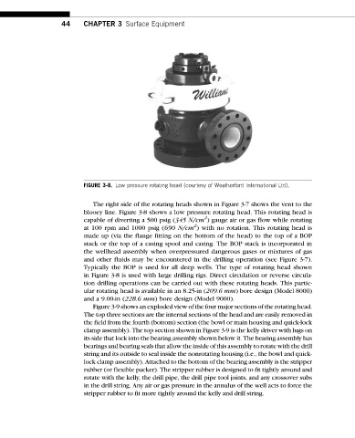
FIGURE 3-8. Low pressure rotating head (courtesy of Weatherford International Ltd).
The right side of the rotating heads shown in Figure 3-7 shows the vent to the
blooey line. Figure 3-8 shows a low pressure rotating head. This rotating head is
2
capable of diverting a 500 psig (345 N/cm ) gauge air or gas flow while rotating
2
at 100 rpm and 1000 psig (690 N/cm ) with no rotation. This rotating head is
made up (via the flange fitting on the bottom of the head) to the top of a BOP
stack or the top of a casing spool and casing. The BOP stack is incorporated in
the wellhead assembly when overpressured dangerous gases or mixtures of gas
and other fluids may be encountered in the drilling operation (see Figure 3-7).
Typically the BOP is used for all deep wells. The type of rotating head shown
in Figure 3-8 is used with large drilling rigs. Direct circulation or reverse circula-
tion drilling operations can be carried out with these rotating heads. This partic-
ular rotating head is available in an 8.25-in (209.6 mm) bore design (Model 8000)
and a 9.00-in (228.6 mm) bore design (Model 9000).
Figure 3-9 shows an exploded view of the four major sections of the rotating head.
The top three sections are the internal sections of the head and are easily removed in
the field from the fourth (bottom) section (the bowl or main housing and quick-lock
clamp assembly). The top section shown in Figure 3-9 is the kelly driver with lugs on
its side that lock into the bearing assembly shown below it. The bearing assembly has
bearings and bearing seals that allow the inside of this assembly to rotate with the drill
string and its outside to seal inside the nonrotating housing (i.e., the bowl and quick-
lock clamp assembly). Attached to the bottom of the bearing assembly is the stripper
rubber (or flexible packer). The stripper rubber is designed to fit tightly around and
rotate with the kelly, the drill pipe, the drill pipe tool joints, and any crossover subs
in the drill string. Any air or gas pressure in the annulus of the well acts to force the
stripper rubber to fit more tightly around the kelly and drill string.