
Page 20 - Aircraft Stuctures for Engineering Student
P. 20
1.2 Notation for forces and stresses 5
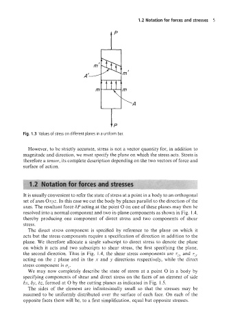
Fig. 1.3 Values of stress on different planes in a uniform bar.
However, to be strictly accurate, stress is not a vector quantity for, in addition to
magnitude and direction, we must specify the plane on which the stress acts. Stress is
therefore a tensor, its complete description depending on the two vectors of force and
surface of action.
1.2 Notation for forces and stresses
It is usually convenient to refer the state of stress at a point in a body to an orthogonal
set of axes Oxyz. In this case we cut the body by planes parallel to the direction of the
axes. The resultant force SP acting at the point 0 on one of these planes may then be
resolved into a normal component and two in-plane components as shown in Fig. 1.4,
thereby producing one component of direct stress and two components of shear
stress.
The direct stress component is specified by reference to the plane on which it
acts but the stress components require a specification of direction in addition to the
plane. We therefore allocate a single subscript to direct stress to denote the plane
on which it acts and two subscripts to shear stress, the first specifying the plane,
the second direction. Thus in Fig. 1.4, the shear stress components are rzx and rzy
acting on the z plane and in the x and y directions respectively, while the direct
stress component is oz.
We may now completely describe the state of stress at a point 0 in a body by
specifying components of shear and direct stress on the faces of an element of side
Sx, by, Sz, formed at 0 by the cutting planes as indicated in Fig. 1.5.
The sides of the element are infinitesimally small so that the stresses may be
assumed to be uniformly distributed over the surface of each face. On each of the
opposite faces there will be, to a first simplification, equal but opposite stresses.