
Page 25 - Aircraft Stuctures for Engineering Student
P. 25
10 Basic elasticity
where I, m and n become the direction cosines of the angles that a normal to the
surface of the body makes with the x, y and z axes respectively.
1.6 Determination of stresses on inclined planes
The complex stress system of Fig. 1.6 is derived from a consideration of the actual
loads applied to a body and is referred to a predetermined, though arbitrary,
system of axes. The values of these stresses may not give a true picture of the severity
of stress at that point so that it is necessary to investigate the state of stress on other
planes on which the direct and shear stresses may be greater.
We shall restrict the analysis to the two-dimensional system of plane stress defined
in Section 1.4.
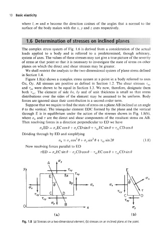
Figure 1.8(a) shows a complex stress system at a point in a body referred to axes
Ox, Oy. All stresses are positive as defined in Section 1.2. The shear stresses T~~
and rYx were shown to be equal in Section 1.3. We now, therefore, designate them
both rxY. The element of side Sx, Sy and of unit thickness is small so that stress
distributions over the sides of the element may be assumed to be uniform. Body
forces are ignored since their contribution is a second-order term.
Suppose that we require to find the state of stress on a plane AB inclined at an angle
8 to the vertical. The triangular element EDC formed by the plane and the vertical
through E is in equilibrium under the action of the stresses shown in Fig. 1.8(b),
where a, and T are the direct and shear components of the resultant stress on AB.
Then resolving forces in a direction perpendicular to ED we have
a,ED = a,EC cos 8 + a,CD sin 8 + T,,EC sin 8 + T,,CD cos 8
Dividing through by ED and simplifying
a, = ax cos2 8 + aY sin2 8 + T~, sin 28
Now resolving forces parallel to ED
TED = a,EC sin 8 - ayCD cos 8 - T,,EC cos 8 + T,,CD sin 8
E
0
(a) (b)
Fig. 1.8 (a) Stresses on a two-dimensional element; (b) stresses on an inclined plane at the point.