
Page 30 - Aircraft Stuctures for Engineering Student
P. 30
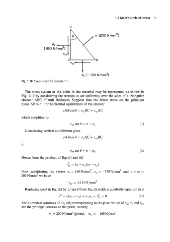
1.8 Mohr's circle of stress  15

                                          B


                                                 t
                                                 cy (-120N/mrn2)
              Fig. 1.10  Stress system for Example 1 .I.


                The stress system at the point  in the material may be  represented as shown in
              Fig.  1.10 by considering the stresses to act uniformly over the sides of a triangular
              element  ABC  of  unit  thickness.  Suppose  that  the  direct  stress  on  the  principal
              plane AB is U. For horizontal equilibrium of the element

                                                        ~
                                                            ~
                                      U~~  cos e = U  x  + Tx.,,~~
              which simplifies to
                                          rXy tan 8 = u - CJ~
                Considering vertical equilibrium gives
                                      uAB sin e = uyAC + T,,BC

              or
                                          Txy cot e =  -                           (ii)

              Hence from the product of Eqs (i) and (ii)
                                         2      - Sx)(U  - (4
                                        Txy  =  (.
              Now  substituting  the  values  nX = 160N/mm2, gy = -120N/mm   2   and  u = c1 =
              200 N/mm2 we have
                                         T~~ = f 113 N/mm2

                Replacing cot B in Eq. (ii) by  1/ tan 8 from Eq. (i) yields a quadratic equation in u
                                    2 - U(Ux - Uy) + UxUy - Try = 0                (iii)
                                                           2
              The numerical solutions of Eq. (iii) corresponding to the given values of ox,   and 74,;
              are the principal stresses at the point, namely
                              aI = 200 N/mm2 (given),  aJr = - 160 N/mm  2