
Page 31 - Aircraft Stuctures for Engineering Student
P. 31
16 Basic elasticity
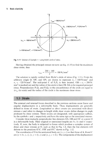
Fig. 1.11 Solution of Example 1 .I using Mohr's circle of stress.
Having obtained the principal stresses we now use Eq. (1.15) to find the maximum
shear stress, thus
The solution is rapidly verified from Mohr's circle of stress (Fig. 1.11). From the
arbitrary origin 0, OP1 and 0P2 are drawn to represent o.~ = 160N/mm2 and
ay = -120N/mm2. The mid-point C of PIP2 is then located. OB = uI = 200N/
mm2 is marked out and the radius of the circle is then CB. OA is the required principal
stress. Perpendiculars PIQl and P2Q2 to the circumference of the circle are equal to
&T~,, (to scale) and the radius of the circle is the maximum shear stress.
The external and internal forces described in the previous sections cause linear and
angular displacements in a deformable body. These displacements are generally
defined in terms of strain. Longitudinal or direct strains are associated with direct
stresses 0 and relate to changes in length while shear strains define changes in angle
produced by shear stresses. These strains are designated, with appropriate suffixes,
by the symbols E and y respectively and have the same sign as the associated stresses.
Consider three mutually perpendicular line elements OA, OB and OC at a point 0
in a deformable body. Their original or unstrained lengths are Sx, Sy and Sz respec-
tively. If, now, the body is subjected to forces which produce a complex system of
direct and shear stresses at 0, such as that in Fig. 1.6, then the line elements will
deform to the positions O'A', O'B' and O'C' shown in Fig. 1.12.
The coordinates of 0 in the unstrained body are (x, y, z) so that those of A, B and C
are (x + Sx, y, z), (x, y + by, z) and (x, y, z + Sz). The components of the displacement