
Page 32 - Aircraft Stuctures for Engineering Student
P. 32
1.9 Strain 17
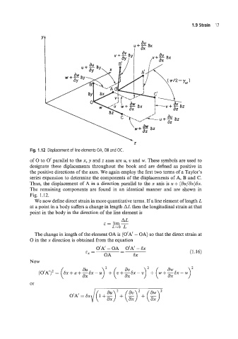
Fig. 1.12 Displacement of line elements OA, OB and OC.
of 0 to 0’ parallel to the x, y and z axes are u, v and w. These symbols are used to
designate these diplacements throughout the book and are defined as positive in
the positive directions of the axes. We again employ the first two terms of a Taylor’s
series expznsion to determine the components of the displacements of A, B and C.
Thus, the displacement of A in a direction parallel to the x axis is zi + (dzr/dx)Sx.
The remaining components are found in an identical manner and are shown in
Fig. 1.12.
We now define direct strain in more quantitative terms. If a line element of length L
at a point in a body suffers a change in length AL then the longitudinal strain at that
point in the body in the direction of the line element is
. AL
E = lim -
L-0 L
The change in length of the element OA is (O’A’ - OA) so that the direct strain at
0 in the x direction is obtained from the equation
O‘A‘ - OA O’A’ - Sx
-
E, = - (1.16)
OA SX
Now
dV dw
- u>’ + (V - v)~ + (W+~SX - w
or