
Page 28 - Aircraft Stuctures for Engineering Student
P. 28
1.8 Mohr’s circle of stress 13
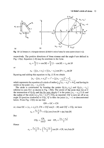
Fig. 1.9 (a) Stresses on a triangular element; (b) Mohr’s circle of stress for stress system shown in (a).
respectively. The positive directions of these stresses and the angle 8 are defined in
Fig. 1.9(a). Equation (1.8) may be rewritten in the form
Squaring and zdding this equation to Eq. (1.9) we obtain
[an - 4 (ax + . + r2 = [i (gx - + <v
)
,
2
I
which represents the equation of a circle of radius 4 and having its
-
centre at the point ((ax - aJ,)/2! 0).
and
The circle is constructed by locating the points Q~(U-~,T,~) Q2(a,, -T~~)
referred to axes Om- as shown in Fig. 1.9(b). The centre of the circle then lies at C
the intersection of Q1Q2 and the Om axis; clearly C is the point ((ax - a,)/2,0) and
the radius of the circle is 4 J(ax - fly)* + h$, as required. CQ‘ is now set off at an
angle 28 (positive clockwise) to CQ1, Q‘ is then the point (ann? -7) as demonstrated
below. From Fig. 1.9(b) we see that
ON = OC + CN
or, since OC = (a, + ay)/2, CN = CQ’cos(p - 28) and CQ’ = CQ1 we have
ax + uy
an = ~ + CQ, (cos p cos 28 + sin p sin 28)
2
But
CQ1=- and CPI = (ax - ffy)
cos p -
Hence
a, = ~ cos 28 + CPl tan p sin 28
2