
Page 36 - Aircraft Stuctures for Engineering Student
P. 36
1.12 Determination of strains on inclined planes 21
Further, by substituting E, = yxz = yyz = 0 in the six equations of compatibility
and noting that E,, E, and y,, are now purely functions of x and y, we are left with
Eq. (1.21), namely
2 d2&,
8 TXY - @E,
axay ax2 +ay2
as the only equation of compatibility in the two-dimensional or plane strain case.
Having defined the strain at a point in a deformable body with reference to an arbi-
trary system of coordinate axes we may calculate direct strains in any given direction
and the change in the angle (shear strain) between any two originally perpendicular
directions at that point. We shall consider the two-dimensional case of plane strain
described in Section 1.1 1.
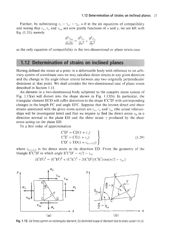
An element in a two-dimensional body subjected to the complex stress system of
Fig. 1.13(a) will distort into the shape shown in Fig. l.l3(b). In particular, the
triangular element ECD will suffer distortion to the shape E’C‘D’ with corresponding
changes in the length FC and angle EFC. Suppose that the known direct and shear
strains associated with the given stress system are E,, E, and yxy (the actual relation-
ships will be investigated later) and that we require to find the direct strain E, in a
direction normal to the plane ED and the shear strain y produced by the shear
stress acting on the plane ED.
To a first order of approximation
C’D’ = CD( 1 + E,)
C’E’ = CE( 1 + E~) (1.29)
E’D‘ = ED(1 + ~,+,p)
~
where E ~ + is /the direct strain in the direction ED. From the geometry of the
~
triangle E’C’D’ in which angle E’C’D’ = 7r/2 - y,,
I ‘2
(E’D’)2 = (C’D’)2 + (C E ) - 2(C’D’)(C’E’) COS(T/~ - yXy)
Y Y
Fig. 1.13 (a) Stress system on rectangular element; (b) distorted shape of element due to stress system in (a).