
Page 237 - Aircraft Stuctures for Engineering Student
P. 237
7.2 loads on structural components 221
Vertical tail providing
directional control
rizontal tail countering
e aircraft’s tendency to
pitch in a vertical plane
Aircraft weight
Fig. 7.3 Principal aerodynamic forces on an aircraft during flight.
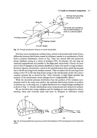
The force on an aerodynamic surface (wing, vertical or horizontal tail) results from a
differential pressure distribution caused by incidence, camber or a combination of both.
Such a pressure distribution, shown in Fig. 7.4(a), has vertical (lift) and horizontal
(drag) resultants acting at a centre of pressure (CP). (In practice, lift and drag are
measured perpendicular and parallel to the flight path respectively.) Clearly the posi-
tion of the CP changes as the pressure distribution varies with speed or wing incidence.
However, there is, conveniently, a point in the aerofoil section about which the moment
due to the lift and drag forces remains constant. Thus we replace the lift and drag forces
acting at the CP by lift and drag forces acting at the aerodynamic centre (AC) plus a
constant moment Mo as shown in Fig. 7.4(b). (Actually, at high Mach numbers the
position of the aerodynamic centre changes due to compressibility effects.)
While the chordwise pressure distribution fixes the position of the resultant aero-
dynamic load in the wing cross-section, the spanwise distribution locates its position
in relation, say, to the wing root. A typical distribution for a wing/fuselage combination
is shown in Fig. 7.5. Similar distributions occur on horizontal and vertical tail surfaces.
We see therefore that wings, tailplane and the fuselage are each subjected to direct,
bending, shear and torsional loads and must be designed to withstand critical
+Lift
Drag
(a) (b)
Fig. 7.4 (a) Pressure distribution around an aerofoil; (b) transference of lift and drag loads to the aerodynamic
centre.