
Page 238 - Aircraft Stuctures for Engineering Student
P. 238
222 Principles of stressed skin construction
Lift
- resultants.
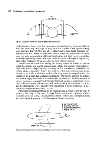
Fig. 7.5 Typical lift distribution for a wingfiuselage combination.
combinations of these. Note that manoeuvres and gusts do not introduce different
loads but result only in changes of magnitude and position of the type of existing
loads shown in Fig. 7.3. Over and above these basic in-flight loads, fuselages may
be pressurized and thereby support hoop stresses, wings may carry weapons and/or
extra fuel tanks with resulting additional aerodynamic and body forces contributing
to the existing bending, shear and torsion, while the thrust and weight of engines may
affect either fuselage or wings depending on their relative positions.
Ground loads encountered in landing and taxiing subject the aircraft to concen-
trated shock loads through the undercarriage system. The majority of aircraft have
their main Undercarriage located in the wings, with a nosewheel or tailwheel in the
vertical plane of symmetry. Clearly the position of the main undercarriage should
be such as to produce minimum loads on the wing structure compatible with the
stability of the aircraft during ground manoeuvres. This may be achieved by locating
the undercarriage just forward of the flexural axis (see Section 1 1.1) of the wing and as
close to the wing root as possible. In this case the shock landing load produces a given
shear, minimum bending plus torsion, with the latter being reduced as far as practic-
able by offsetting the torque caused by the vertical load in the undercarriage leg by a
torque in an opposite sense due to braking.
Other loads include engine thrust on the wings or fuselage which acts in the plane of
symmetry but may, in the case of engine failure, cause severe fuselage bending
moments, as shown in Fig. 7.6; concentrated shock loads during a catapult launch;
and hydrodynamic pressure on the fuselages or floats of seaplanes.
j, Vertical tail load
balancing moment
due to unsymmetrical
engine thrust
Fig. 7.6 Fuselage and wing bending caused by an unsymmetrical engine load.